TP-6255 7/06
80
Section 9 Generator Disassembly/Reassembly
9. Disconnect wiring harness plugs P1, P15, and P16
from the ADC 2100.
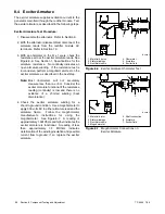
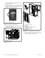
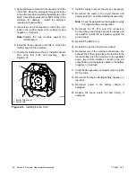
10. Loosen and remove the four controller mounting
screws at the front of the controller.
See
Figure 9-2. Remove the controller.
1
tp6196
1. Controller mounting screws (4 ea.)
Figure 9-2
ADC 2100 Mounting Screws
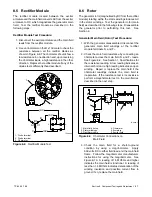
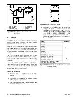
11. Remove the junction box louvered panel.
See
Figure 9-3 and Figure 9-4.
1
2
1. ADC 2100
2. Junction box louvered panel
Figure 9-3
Covers
1
1. Junction box louvered panel
2. SCR module
3. Relay board
4. Engine harness-to-controller connection
5. Generator set master switch
6. ADC 2100
7. Line circuit breaker plate
8. Junction box
6
7
8
3
2
5
4
Figure 9-4
Advanced Digital Control (ADC 2100)
12. Remove the junction box, SCR module, and relay
board as necessary. See Figure 9-4.
Содержание 6.5-27EFOZD
Страница 1: ...Marine Generator Sets Models 8 32EOZD 6 5 27EFOZD TP 6255 7 06a Service ...
Страница 12: ...TP 6255 7 06 12 Service Assistance Notes ...
Страница 22: ...TP 6255 7 06 22 Section 1 Specifications Notes ...
Страница 28: ...TP 6255 7 06 28 Section 3 Intake and Exhaust System Notes ...
Страница 62: ...TP 6255 7 06 62 Section 7 Controller Notes ...
Страница 78: ...TP 6255 7 06 78 Section 8 Component Testing and Adjustment Notes ...
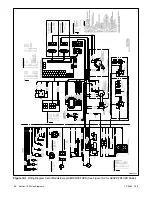
Страница 87: ...TP 6255 7 06 87 Section 10 Wiring Diagrams GM46351 Figure 10 2 Wiring Diagram for 9EOZD 7EFOZD Model ...
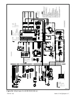
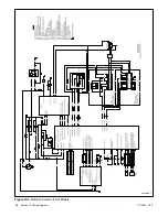
Страница 88: ...TP 6255 7 06 88 Section 10 Wiring Diagrams ADV6845A F Figure 10 3 Wiring Schematic for All Models ...
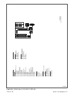
Страница 89: ...TP 6255 7 06 89 Section 10 Wiring Diagrams ADV6845B F Figure 10 4 Wiring Diagram Schematic for All Models ...
Страница 92: ...TP 6255 7 06 92 Section 10 Wiring Diagrams Notes ...
Страница 100: ...TP 6255 7 06 100 ...
Страница 101: ...TP 6255 7 06 101 ...
Страница 102: ...TP 6255 7 06 102 ...
Страница 103: ...TP 6255 7 06 103 ...

