TP-6255 7/06
48
Section 7 Controller
7.3.3
Running Sequence
When the engine speed reaches 750 rpm, the crank
relay deenergizes and the crank LED (3) turns off.
When the output voltage on leads 11 and 44 (for 1-phase
models) or leads 7, 8, and 9 (for 3-phase models)
reaches about 30 VAC, the flash relay deenergizes and
the flash LED (2) turns off.
7.3.4
Stopping Sequence, Master
Switch Moved to OFF/RESET
Place the generator master switch in the OFF/RESET
position. The run relay deenergizes and the run LED (1)
turns off. The generator set stops.
7.3.5
Stopping Sequence, Remote Stop
If the generator set is running, momentarily closing the
remote start/stop contacts deenergizes the run relay
and the run LED (1) turns off, but the controller does not
power down.
The controller remains powered and
displays the engine runtime hours.
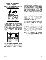
Note: For units with serial numbers before 2051415:
Disconnecting the P7 jumper will allow the
controller to power down 48 hours after generator
set shutdown.
See Section 7.8, Continuous
Power Mode.
Note: For units with serial numbers 2051415 and
later:
If the ADC 2100 is configured for a CAN gauge,
the controller will not power down (if the master
switch is in the AUTO position).
If the ADC 2100 is not configured for a CAN
gauge, the controller will power down after
48 hours (if the master switch is in the AUTO
position). If the generator has been started, the
controller will power down 48 hours after the
generator stops.
7.4 Faults
7.4.1
Fault Shutdowns
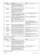
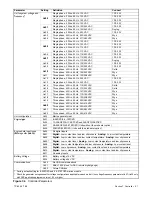
Under the fault conditions listed in Figure 7-4, the ADC
displays a fault code and the generator set shuts down.
Always identify and correct the cause of a fault
shutdown before restarting the generator set. Refer to
Section 6, Troubleshooting, for instructions to identify
and correct the cause of the fault.
To restart the generator set, first move the generator set
master switch to the OFF/RESET position to reset the
controller.
Note: For units with serial numbers before 2051415:
If the power jumper is removed and the controller
powers down after a fault shutdown, move the
master switch to the OFF/RESET position and
then to the RUN position to display the fault code.
Moving the master switch to the OFF position
again will clear the fault. See Section 7.8 for more
information on the continuous power mode
jumper.
7.4.2
Warnings
The fault conditions listed in Figure 7-5 will cause the
controller to display a fault code but will not shut down
the generator set.
Содержание 6.5-27EFOZD
Страница 1: ...Marine Generator Sets Models 8 32EOZD 6 5 27EFOZD TP 6255 7 06a Service ...
Страница 12: ...TP 6255 7 06 12 Service Assistance Notes ...
Страница 22: ...TP 6255 7 06 22 Section 1 Specifications Notes ...
Страница 28: ...TP 6255 7 06 28 Section 3 Intake and Exhaust System Notes ...
Страница 62: ...TP 6255 7 06 62 Section 7 Controller Notes ...
Страница 78: ...TP 6255 7 06 78 Section 8 Component Testing and Adjustment Notes ...
Страница 87: ...TP 6255 7 06 87 Section 10 Wiring Diagrams GM46351 Figure 10 2 Wiring Diagram for 9EOZD 7EFOZD Model ...
Страница 88: ...TP 6255 7 06 88 Section 10 Wiring Diagrams ADV6845A F Figure 10 3 Wiring Schematic for All Models ...
Страница 89: ...TP 6255 7 06 89 Section 10 Wiring Diagrams ADV6845B F Figure 10 4 Wiring Diagram Schematic for All Models ...
Страница 92: ...TP 6255 7 06 92 Section 10 Wiring Diagrams Notes ...
Страница 100: ...TP 6255 7 06 100 ...
Страница 101: ...TP 6255 7 06 101 ...
Страница 102: ...TP 6255 7 06 102 ...
Страница 103: ...TP 6255 7 06 103 ...

