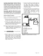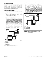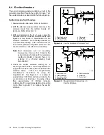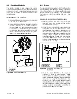
TP-6255 7/06
54
Section 7 Controller
TP6196
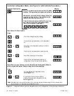
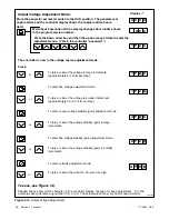
Move the generator set master switch to the RUN position. The generator set
engine starts and the controller display shows the engine runtime hours.
Display :*
or
or
To raise or lower the voltage in large increments
(approximately 5--7 volts per step).
To enter fine voltage adjustment mode.
To raise or lower the voltage in smaller increments
(approximately 0.5--0.7 volts per step).
To enter coarse voltage stability (gain) adjustment mode.
or
To raise or lower the voltage stability (gain) in large
increments.
To enter fine voltage stability (gain) adjustment mode.
or
To raise or lower the voltage stability (gain) in smaller
increments.
To enter volts/Hz adjustment mode.
To raise or lower the volts/Hz: 00=low; 09= high
or
Hold:
Wait about 5 seconds until the display changes from runtime hours
to the program version number.
Press the down arrow key and then the up arrow key 3 times to enter the
adjustment mode. (This is the controller “password.”)
x x
x x x x
1 P
1 P
2 P
* Shaded boxes show which character in the controller display changes for each adjustment.
X
in the
examples above denotes any number from 0 to 9. The actual values may vary from model-to-model.
x.
2 P
3 P 0
The controller is now in the voltage coarse adjustment mode.
Press:
1 P
To save, see Figure 7-9.
x x
x x
x
x
x x
x
x
x
Output Voltage Adjustment Mode:
Figure 7-10
Output Voltage Adjustments
Содержание 6.5-27EFOZD
Страница 1: ...Marine Generator Sets Models 8 32EOZD 6 5 27EFOZD TP 6255 7 06a Service ...
Страница 12: ...TP 6255 7 06 12 Service Assistance Notes ...
Страница 22: ...TP 6255 7 06 22 Section 1 Specifications Notes ...
Страница 28: ...TP 6255 7 06 28 Section 3 Intake and Exhaust System Notes ...
Страница 62: ...TP 6255 7 06 62 Section 7 Controller Notes ...
Страница 78: ...TP 6255 7 06 78 Section 8 Component Testing and Adjustment Notes ...
Страница 87: ...TP 6255 7 06 87 Section 10 Wiring Diagrams GM46351 Figure 10 2 Wiring Diagram for 9EOZD 7EFOZD Model ...
Страница 88: ...TP 6255 7 06 88 Section 10 Wiring Diagrams ADV6845A F Figure 10 3 Wiring Schematic for All Models ...
Страница 89: ...TP 6255 7 06 89 Section 10 Wiring Diagrams ADV6845B F Figure 10 4 Wiring Diagram Schematic for All Models ...
Страница 92: ...TP 6255 7 06 92 Section 10 Wiring Diagrams Notes ...
Страница 100: ...TP 6255 7 06 100 ...
Страница 101: ...TP 6255 7 06 101 ...
Страница 102: ...TP 6255 7 06 102 ...
Страница 103: ...TP 6255 7 06 103 ...

