


TP-6255 7/06
76
Section 8 Component Testing and Adjustment
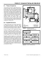
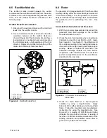
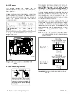
8.12 Fuses
The
engine
harness
(or
junction
box
for
9EOZD/7EFOZD models) contains three inline fuses.
See Figure 8-27.
Always identify and correct the cause of a blown fuse
before restarting the generator set. Refer to Section 6,
Troubleshooting, for conditions that may indicate a
blown fuse.
Replace blown fuses with identical
replacement parts.
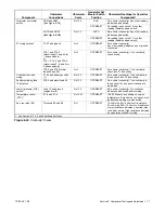
Fuse
Label
Part
Number
Location
Auxiliary Winding,
10 amps
F1
358337
Lead 55
Relay Interface Board,
10 amps
F2
223316
Lead PF2
Controller, 10 amps
F3
223316
Lead PF3
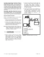
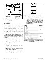
* See Figure 8-28 for 9EOZD/7EFOZD model fuse location.
Figure 8-27
Fuses
1
ADV6967-A
1. Fuses
Figure 8-28
Fuse Location on 9EOZD/7EFOZD
Model
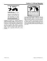
8.13 Continuity Checks
Hazardous voltage.
Can cause severe injury or death.
Operate the generator set only when
all guards and electrical enclosures
are in place.
Moving rotor.
WARNING
Short circuits.
Hazardous voltage/current can cause
severe injury or death.
Short circuits can cause bodily injury
and/or equipment damage
.
Do not contact electrical
connections with tools or jewelry while making adjustments or
repairs. Remove all jewelry before servicing the equipment.
To further check generator set components, disconnect
the battery and remove wiring harness plugs from the
ADC circuit board.
Use an ohmmeter to check the
continuity of the components listed in Figure 8-30. Also
see Section 10, Wiring Diagrams.
Figure 8-30 gives resistance readings for functional
components. A zero reading on the ohmmeter indicates
continuity. No ohmmeter reading indicates very high
resistance or an open circuit.
A measurement that
varies significantly from the value shown in the table
indicates
a
faulty
component;
replace
faulty
components.
Note:
Disconnect the generator set battery before
performing continuity checks to prevent damage
to the ohmmeter.
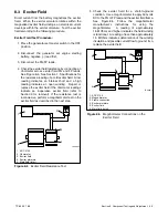
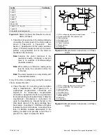
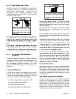
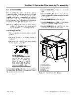
3
2
1
3
2
1
Master Switch in
RUN Position
Master Switch in
AUTO Position
Zero ohms (continuity) across
RUN and VBAT terminals
Zero ohms (continuity) across
VBAT and AUTO terminals
AUT
O
RUN
AUT
O
RUN
Back View
Back View
VBA
T
VBA
T
Figure 8-29
Generator Set Master Switch Continuity
Checks
Содержание 6.5-27EFOZD
Страница 1: ...Marine Generator Sets Models 8 32EOZD 6 5 27EFOZD TP 6255 7 06a Service ...
Страница 12: ...TP 6255 7 06 12 Service Assistance Notes ...
Страница 22: ...TP 6255 7 06 22 Section 1 Specifications Notes ...
Страница 28: ...TP 6255 7 06 28 Section 3 Intake and Exhaust System Notes ...
Страница 62: ...TP 6255 7 06 62 Section 7 Controller Notes ...
Страница 78: ...TP 6255 7 06 78 Section 8 Component Testing and Adjustment Notes ...
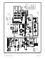
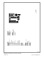
Страница 87: ...TP 6255 7 06 87 Section 10 Wiring Diagrams GM46351 Figure 10 2 Wiring Diagram for 9EOZD 7EFOZD Model ...
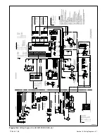
Страница 88: ...TP 6255 7 06 88 Section 10 Wiring Diagrams ADV6845A F Figure 10 3 Wiring Schematic for All Models ...
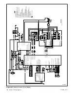
Страница 89: ...TP 6255 7 06 89 Section 10 Wiring Diagrams ADV6845B F Figure 10 4 Wiring Diagram Schematic for All Models ...
Страница 92: ...TP 6255 7 06 92 Section 10 Wiring Diagrams Notes ...
Страница 100: ...TP 6255 7 06 100 ...
Страница 101: ...TP 6255 7 06 101 ...
Страница 102: ...TP 6255 7 06 102 ...
Страница 103: ...TP 6255 7 06 103 ...