


TP-6255 7/06
77
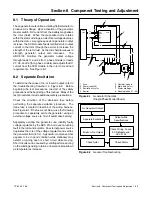
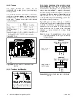
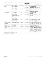
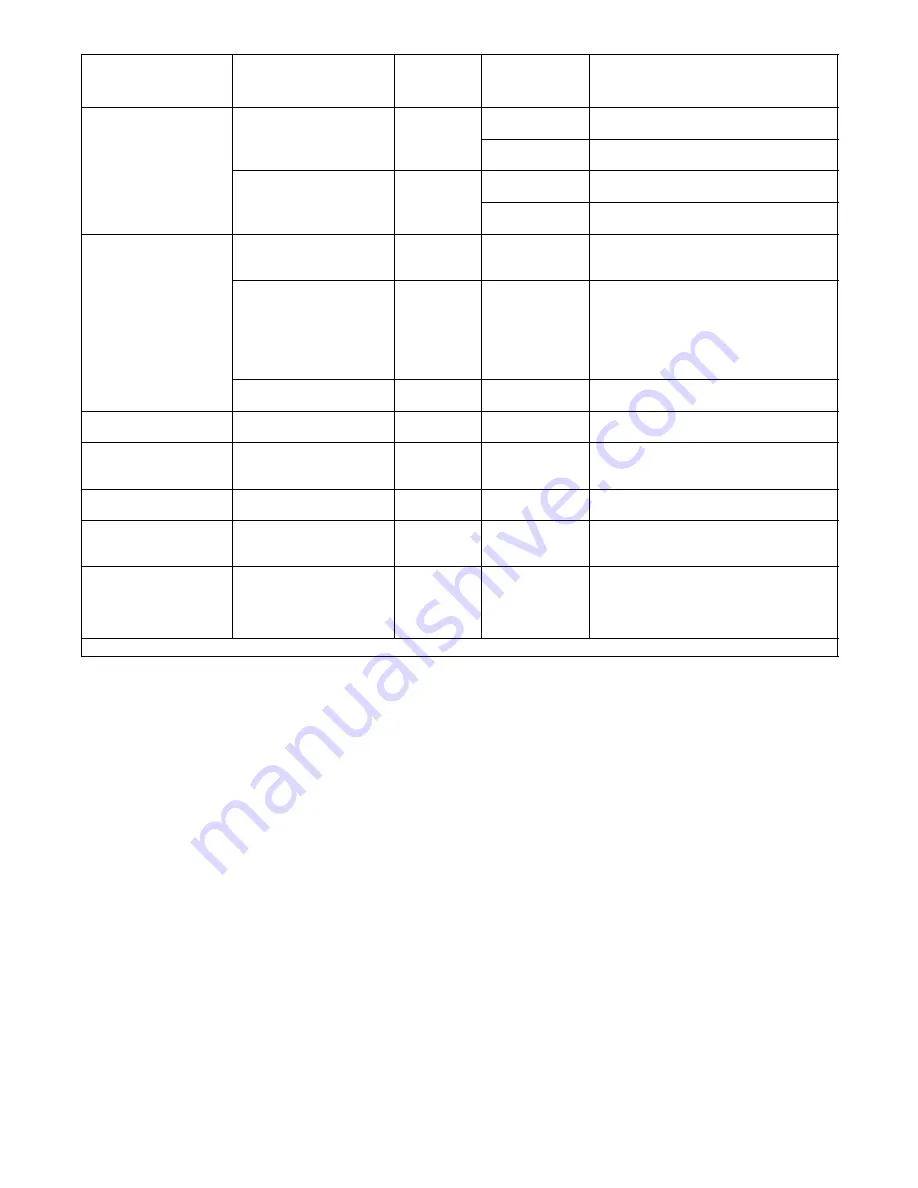
Section 8 Component Testing and Adjustment
Component
Ohmmeter
Connections
Ohmmeter
Scale
Generator Set
Master Switch
Position
Ohmmeter Readings for Operative
Components*
Generator set master
switch
RUN and VBAT
(See Figure 8-29)
R x 100
RUN
Zero ohms (continuity). Any other reading
indicates a bad switch.
switch
(See Figure 8 29)
OFF/RESET
No reading (open circuit). Any other
reading indicates a bad switch.
AUTO and VBAT
(See Figure 8-29)
R x 100
AUTO
Zero ohms (continuity). Any other reading
indicates a bad switch.
(S
g
8 9)
OFF/RESET
No reading (open circuit). Any other
reading indicates a bad switch.
P1 wiring harness
P1-27 and ground
R x 1
OFF/RESET
Zero ohms (continuity)
Any other reading indicates a poor ground
connection.
P15-1 and P15-3
(stator leads 11 and 44 for
1-phase models)
or
P15-1, P15-2, and P15-3
(stator leads 7, 8, and 9 for
3-phase models)
R x 1
OFF/RESET
Zero ohms (continuity). If no continuity,
check wiring.
P16-3 and P16-6 (stator
leads 55 and 66)
R x 1
OFF/RESET
Zero ohms (continuity). If no continuity,
check fuse F1 and wiring.
Controller fuse and
wiring
P1-24 and battery positive
(+)
R x 100
OFF/RESET
Zero ohms (continuity). If no continuity is
found, check fuse F3 and wiring.
Auxiliary winding fuse
10 amp fuse
P16-3 and stator lead 55
R x 100
OFF/RESET
Zero ohms (continuity). If no continuity is
found, check for an open circuit and/or a
blown fuse.
Low oil pressure (LOP)
switch *
Lead 13 and ground
(engine block)
R x 100
OFF/RESET
Zero ohms (continuity). No continuity
indicates a bad switch and/or wiring.
Temperature sensor
(CTS) *
P1-8 and P1-9
R x 1000
OFF/RESET
180--2500 ohms, depending on engine
temperature. Zero ohms or an open circuit
indicates bad wiring or a bad switch.
Aux. run relay (K5)
Terminals 85 and 86
R x 1
OFF/RESET
12-volt relay: 85
±
5 ohms coil resistance
24-volt relay: 305
±
15 ohms coil resistance
Lower resistance indicates a shorted relay
coil and/or wiring. High resistance indicates
an open relay coil and/or wiring.
* See Section 8.11.2, Fault Shutdown Switches
Figure 8-30
Continuity Checks
Содержание 6.5-27EFOZD
Страница 1: ...Marine Generator Sets Models 8 32EOZD 6 5 27EFOZD TP 6255 7 06a Service ...
Страница 12: ...TP 6255 7 06 12 Service Assistance Notes ...
Страница 22: ...TP 6255 7 06 22 Section 1 Specifications Notes ...
Страница 28: ...TP 6255 7 06 28 Section 3 Intake and Exhaust System Notes ...
Страница 62: ...TP 6255 7 06 62 Section 7 Controller Notes ...
Страница 78: ...TP 6255 7 06 78 Section 8 Component Testing and Adjustment Notes ...
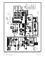
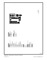
Страница 87: ...TP 6255 7 06 87 Section 10 Wiring Diagrams GM46351 Figure 10 2 Wiring Diagram for 9EOZD 7EFOZD Model ...
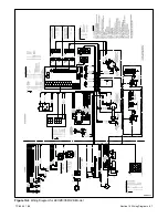
Страница 88: ...TP 6255 7 06 88 Section 10 Wiring Diagrams ADV6845A F Figure 10 3 Wiring Schematic for All Models ...
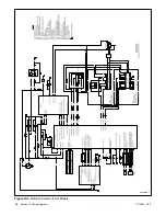
Страница 89: ...TP 6255 7 06 89 Section 10 Wiring Diagrams ADV6845B F Figure 10 4 Wiring Diagram Schematic for All Models ...
Страница 92: ...TP 6255 7 06 92 Section 10 Wiring Diagrams Notes ...
Страница 100: ...TP 6255 7 06 100 ...
Страница 101: ...TP 6255 7 06 101 ...
Страница 102: ...TP 6255 7 06 102 ...
Страница 103: ...TP 6255 7 06 103 ...