


TP-6255 7/06
53
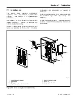
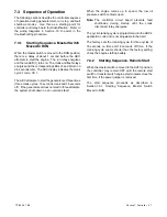
Section 7 Controller
or
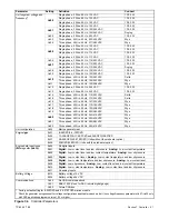
To set the engine data input type.
To enter battery voltage selection mode.
or
To toggle between 12 and 24 VDC.
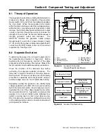
To enter communications selection mode.
or
To set the communications parameter mode.
To enter SAVE mode. Go to Figure 7-9.
E d 0
x
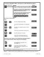
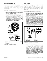
Pressing the up arrow key at the Adnc display (See Figure 7-7) puts you into
the Advanced Configuration Mode.
Press:
B t 1 2
C n 0 0
S A V E
B t 2 4
12-volt models
24-volt models
Note:
Shaded boxes show which number in the controller display changes when the up or down arrow
key is pressed.
“x”
denotes any number from 0 to 9.
Figure 7-8
Advanced Configuration Mode (engine data input types, battery voltage, and engine
communications)
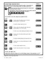
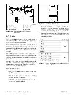
To save changes.
To discard changes without saving.
or
Note:
Be sure to save your settings before exiting the configuration mode. The controller reverts to the
last
saved
settings when the master switch is moved to the OFF/RESET position.
*
x
in the runtime hours display above denotes any number from 0 to 9.
S A V E
Y E S
Now move the master switch to OFF/RESET.
n o
There are 3 options when the display says SAVE:
Press:
x x
x
x
or
To return to the first parameter, system voltage/frequency Uu,
to check or change settings before saving. See Figure 7-7.
U u 0
x
“Yes”or “no” flashes when the up or down arrow is pressed and then
the controller exits the configuration mode. The display returns to
the runtime hours.
Figure 7-9
Save Mode (after configuring generator set parameters)
Содержание 6.5-27EFOZD
Страница 1: ...Marine Generator Sets Models 8 32EOZD 6 5 27EFOZD TP 6255 7 06a Service ...
Страница 12: ...TP 6255 7 06 12 Service Assistance Notes ...
Страница 22: ...TP 6255 7 06 22 Section 1 Specifications Notes ...
Страница 28: ...TP 6255 7 06 28 Section 3 Intake and Exhaust System Notes ...
Страница 62: ...TP 6255 7 06 62 Section 7 Controller Notes ...
Страница 78: ...TP 6255 7 06 78 Section 8 Component Testing and Adjustment Notes ...
Страница 87: ...TP 6255 7 06 87 Section 10 Wiring Diagrams GM46351 Figure 10 2 Wiring Diagram for 9EOZD 7EFOZD Model ...
Страница 88: ...TP 6255 7 06 88 Section 10 Wiring Diagrams ADV6845A F Figure 10 3 Wiring Schematic for All Models ...
Страница 89: ...TP 6255 7 06 89 Section 10 Wiring Diagrams ADV6845B F Figure 10 4 Wiring Diagram Schematic for All Models ...
Страница 92: ...TP 6255 7 06 92 Section 10 Wiring Diagrams Notes ...
Страница 100: ...TP 6255 7 06 100 ...
Страница 101: ...TP 6255 7 06 101 ...
Страница 102: ...TP 6255 7 06 102 ...
Страница 103: ...TP 6255 7 06 103 ...


