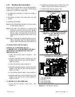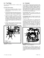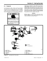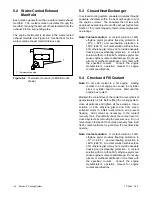
TP-6255 7/06
29
Section 4 Fuel System
Section 4 Fuel System
4.1 General
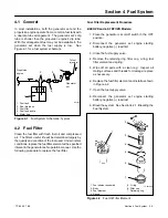
In most installations, both the generator set and the
propulsion engine operate from a common fuel tank with
a dual dip tube arrangement. The generator set’s dip
tube is shorter than the propulsion engine’s dip tube.
With this arrangement fuel may not be available to the
generator set when the fuel supply is low.
See
Figure 4-1 for a fuel system schematic.
Generator
set
Propulsion
engine
1
2
4
3
To fuel
injectors
1. Fuel tank
2. Dual dip tubes
3. Fuel filter
4. Fuel feed pump
5. Water trap
607141
5
Figure 4-1
Fuel System Schematic, Typical
4.2 Fuel Filter
Clean the fuel filter with fresh fuel oil and compressed
air. The filter’s useful life will be determined largely by
the quality and condition of the fuel used. Under normal
conditions, replace the fuel filter element at the specified
interval in the generator set’s operation manual. Use the
following procedure to replace the fuel filter.
Fuel Filter Replacement Procedure
8/9EOZD and 6.5/7EFOZD Models:
1. Place the generator set on/off switch in the OFF
position.
2. Disconnect the generator set engine starting
battery, negative (--) lead first.
3. Close the fuel supply valve.
4. Remove the retaining ring, filter cup, o-ring, fuel
filter element and spring.
5. Wipe off all parts with a clean rag.
Inspect all
mating surfaces and threads for damage; replace
as necessary.
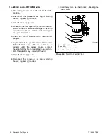
6. Replace the fuel filter element and install as shown
in Figure 4-2.
7. Open the fuel supply valve.
8. Reconnect the generator set engine starting
battery, negative (--) lead last.
9. Bleed the system. See Section 4.2.1, Bleeding the
Fuel System.
1
TP-561633
1. Fuel strainer assembly
2. Body
3. Fuel element
4. Spring
5. O-ring
6. Filter cup
7. Retaining ring
2
3
4
5
6
7
Figure 4-2
Fuel Oil Filter Element
Содержание 6.5-27EFOZD
Страница 1: ...Marine Generator Sets Models 8 32EOZD 6 5 27EFOZD TP 6255 7 06a Service ...
Страница 12: ...TP 6255 7 06 12 Service Assistance Notes ...
Страница 22: ...TP 6255 7 06 22 Section 1 Specifications Notes ...
Страница 28: ...TP 6255 7 06 28 Section 3 Intake and Exhaust System Notes ...
Страница 62: ...TP 6255 7 06 62 Section 7 Controller Notes ...
Страница 78: ...TP 6255 7 06 78 Section 8 Component Testing and Adjustment Notes ...
Страница 87: ...TP 6255 7 06 87 Section 10 Wiring Diagrams GM46351 Figure 10 2 Wiring Diagram for 9EOZD 7EFOZD Model ...
Страница 88: ...TP 6255 7 06 88 Section 10 Wiring Diagrams ADV6845A F Figure 10 3 Wiring Schematic for All Models ...
Страница 89: ...TP 6255 7 06 89 Section 10 Wiring Diagrams ADV6845B F Figure 10 4 Wiring Diagram Schematic for All Models ...
Страница 92: ...TP 6255 7 06 92 Section 10 Wiring Diagrams Notes ...
Страница 100: ...TP 6255 7 06 100 ...
Страница 101: ...TP 6255 7 06 101 ...
Страница 102: ...TP 6255 7 06 102 ...
Страница 103: ...TP 6255 7 06 103 ...


