TP-6255 7/06
47
Section 7 Controller
7.3 Sequence of Operation
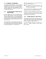
The following sections describe the controller sequence
of operation during generator start, run, stop, and fault
shutdown modes.
Use this as a starting point for
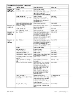
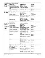
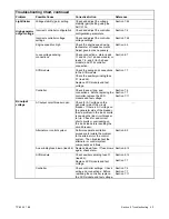
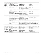
controller and relay board fault identification. Refer to
the wiring diagrams in Section 10 to assist in the
troubleshooting procedure.
7.3.1
Starting Sequence, Master Switch
Moved to RUN
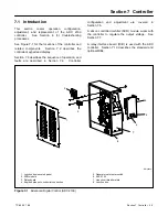
When the master switch is moved to the RUN position,
there is a delay of about 1 second before the ADC
attempts to start the engine. The run relay energizes
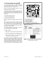
and the run LED (1) turns on. The crank and flash relays
energize and the corresponding LEDs (2 and 3) turn on
0.5 seconds later. The ADC display indicates the crank
cycle 1 code, CC 1.
The ADC attempts to start the generator set three times
(three crank cycles, 15 seconds crank and 15 seconds
off). If the generator set does not start in three attempts,
the system shuts down on an overcrank fault.
When the engine comes up to speed, the low oil
pressure switch contacts open.
Note:
The controller circuit board prevents fault
shutdowns
during
startup
until
the
crank
disconnect relay energizes.
The cyclic cranking cycle is programmed into the ADC’s
application code and is not adjustable in the field.
The factory sets the cranking cycle for three cycles of
15 seconds on time and 15 seconds off time. If the
cranking cycle seems shorter than the factory setting,
check the engine starting battery.
7.3.2
Starting Sequence, Remote Start
When the master switch is moved to the AUTO position,
the controller may remain OFF until the remote start
switch or transfer switch engine start contacts close the
first time, if the power jumper is removed.
The
start
sequence
proceeds
as
described
in
Section 7.3.1,
Starting
Sequence,
Master
Switch
Moved to RUN.
Содержание 6.5-27EFOZD
Страница 1: ...Marine Generator Sets Models 8 32EOZD 6 5 27EFOZD TP 6255 7 06a Service ...
Страница 12: ...TP 6255 7 06 12 Service Assistance Notes ...
Страница 22: ...TP 6255 7 06 22 Section 1 Specifications Notes ...
Страница 28: ...TP 6255 7 06 28 Section 3 Intake and Exhaust System Notes ...
Страница 62: ...TP 6255 7 06 62 Section 7 Controller Notes ...
Страница 78: ...TP 6255 7 06 78 Section 8 Component Testing and Adjustment Notes ...
Страница 87: ...TP 6255 7 06 87 Section 10 Wiring Diagrams GM46351 Figure 10 2 Wiring Diagram for 9EOZD 7EFOZD Model ...
Страница 88: ...TP 6255 7 06 88 Section 10 Wiring Diagrams ADV6845A F Figure 10 3 Wiring Schematic for All Models ...
Страница 89: ...TP 6255 7 06 89 Section 10 Wiring Diagrams ADV6845B F Figure 10 4 Wiring Diagram Schematic for All Models ...
Страница 92: ...TP 6255 7 06 92 Section 10 Wiring Diagrams Notes ...
Страница 100: ...TP 6255 7 06 100 ...
Страница 101: ...TP 6255 7 06 101 ...
Страница 102: ...TP 6255 7 06 102 ...
Страница 103: ...TP 6255 7 06 103 ...

