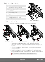


PAGE 64 of 140
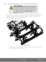
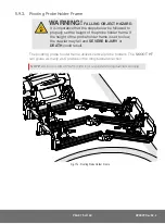
To adjust the probe holder’s force, follow these steps:
NOTE:
Do not perform this operation on scanning surface.
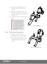
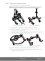
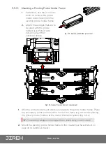
1.
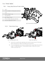
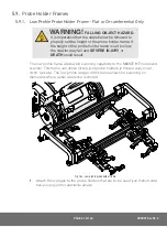
Ensure the probe holder is in the upright latched position
(Fig. 146)
.
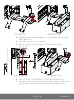
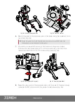
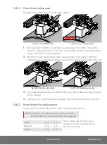
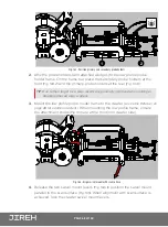
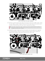
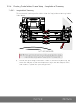
2.
Lift probe holder slightly and press the latch button
(Fig. 150)
to release
the probe holder the full 45° degrees
.
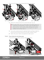
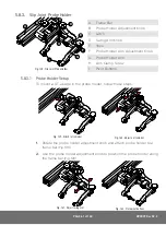
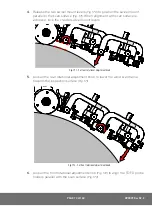
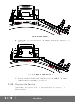
3.
Insert the short arm of a 3 mm hex wrench into the 3 mm slot
(Fig. 151)
.
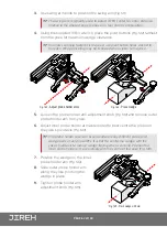
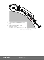
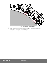
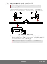
4.
Place the 2 mm hex wrench into the force adjustment screw
(Fig. 152)
.
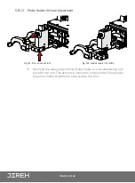
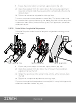
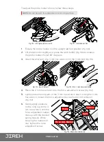
5.
Lightly press the long arm of the 3 mm hex wrench down. Using the 2 mm
hex wrench, loosen the force adjustment screw but do not remove it
(Fig. 153)
.
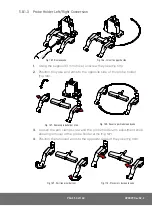
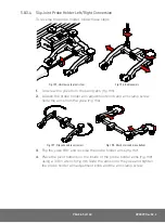
6.
Gently apply pressure
on the long leg of the 3
mm hex wrench until the
force adjustment marker
lines up with the desired
spring tension. While
keeping the markers in
line, tighten the force
adjustment screw.
Fig. 150 - Lift slightly and press Latch
Fig. 151 - Unlatched position
Fig. 152 - Insert hex tools
Fig. 153 - Press 3 mm hex wrench down
Heavy
Medium
Light
Force Adj. Marker
Heavy
Medium
Light
Force Adj. Marker
Fig. 154 - Choose desired tension