


PAGE 58 of 140
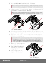
1.
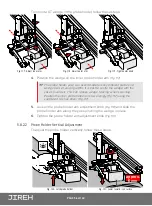
Ensure the probe holder is in latched, upper position
(Fig. 120)
.
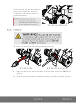
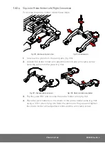
2.
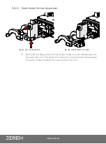
Using the supplied 3 mm hex driver loosen the transverse adjustment
screw
(Fig. 124)
and rotate the yoke about the vertical shaft achieving the
desired angle.
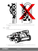
3.
Tighten the transverse adjustment screw
(Fig. 125)
.
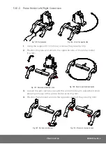
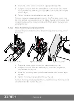
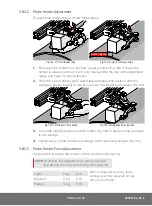
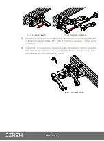
To return the transverse adjustment to neutral
(90°)
. The probe holder must
be in the latched, upper position
(Fig. 120)
. Rotate the yoke until the stop post
contacts the base of the probe holder
(Fig. 126)
. Then tighten the transverse
adjustment screw.
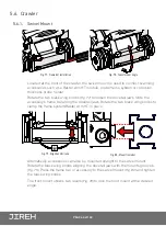
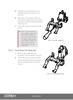
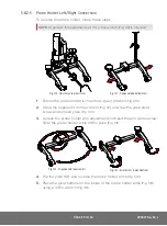
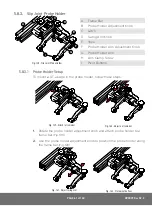
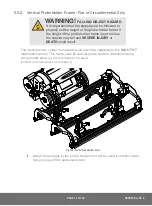
5.8.2.4 Probe Holder Longitudinal Adjustment
To adjust the probe holder’s vertical angle for longitudinal scanning, follow
these steps:
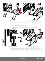
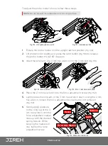
1.
Ensure the probe holder is in latched, upper position
(Fig. 120)
.
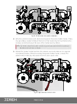
2.
Using the supplied 3 mm hex driver
(Fig. 37)
, loosen the longitudinal
adjustment screw
(Fig. 127)
.
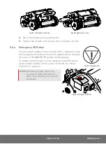
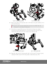
3.
Rotate the main body of the probe holder until it is at the desired angle
(Fig. 128)
.
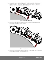
4.
Tighten the longitudinal adjustment screw
(Fig. 128)
.
To return the longitudinal adjustment to neutral (90°). Line up the longitudinal
adjustment indicator markers
(Fig. 129)
.
Fig. 127 - Loosen 3 mm screw
Fig. 128 - Rotate to position
Fig. 129 - Line up markers