59
item Controller BL 1-04 /C
― Product manual
▪ The outer shield is always connected to PE (connector housing) on the servo drive side.
▪ The three inner shields are connected to PIN 3 of X2A on one side of the servo drive.
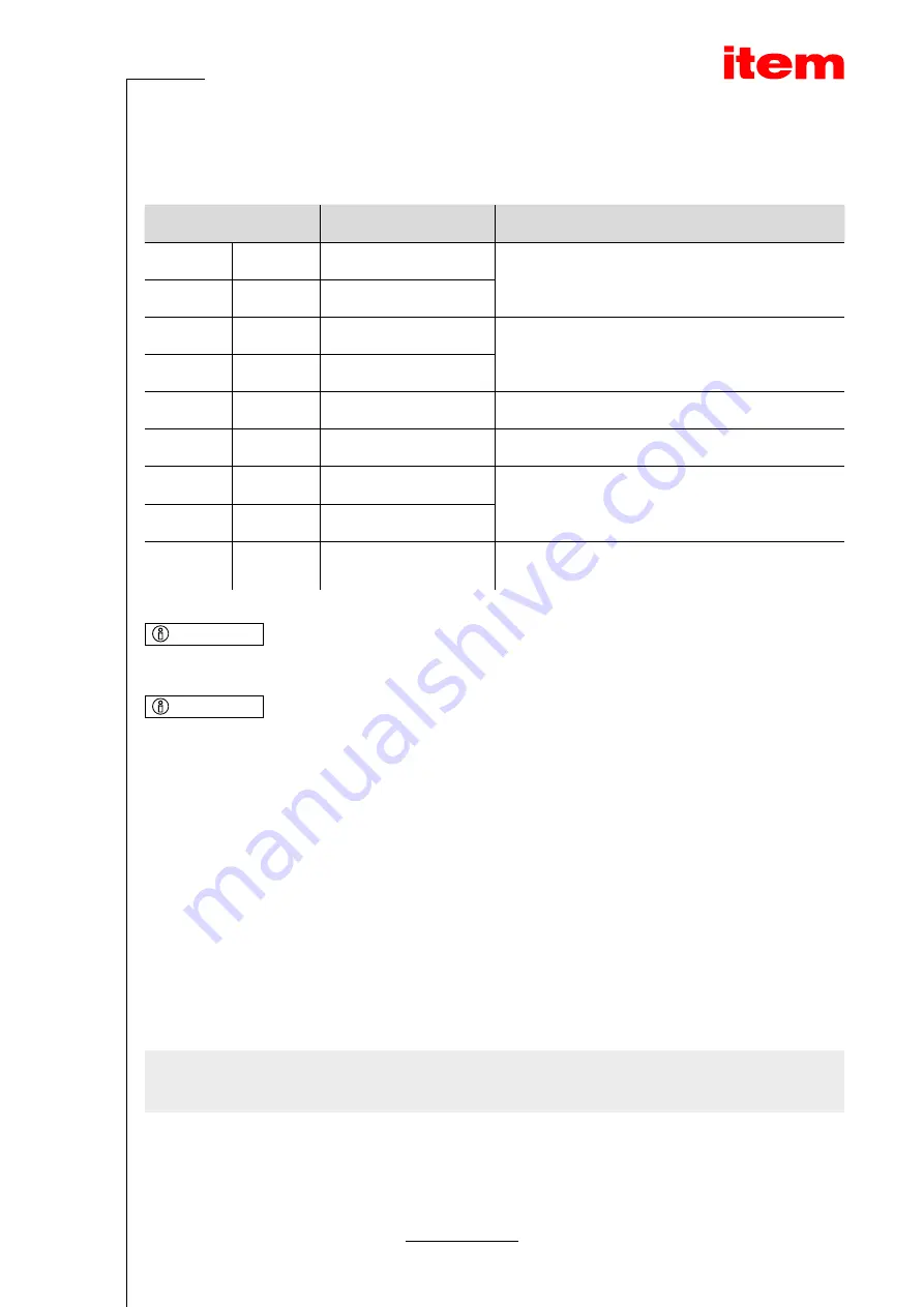
Pin
Name
Specification
1
S2
SINE track signal, differential
Analogue Hall sensor (SINE)
6
S4
2
S1
COSINE track signal, differential
Analogue Hall sensor (COSINE)
7
S3
3
GND
Shield for signal pairs (inner shield)
8
MT-
Temperature sensor reference potential
4
R1
Carrier signal for the resolver
9
R2
5
MT+
Motor temperature sensor, normally closed contact, PTC,
NTC, KTY
INFO
Only one motor temperature sensor can be connected
The motor temperature sensor can either be connected to X2A, X2B or X6. It is not possible to connect several sensors at a time.
INFO
Avoiding EMC interferences
The outer cable shield must be connected to the housing of the angle encoder connector with the greatest possible surface
area (with low impedance).
Cable type and configuration [X2A]
The cable names that are stated refer to cables made by Lapp. However, it is also possible to use comparable cables from
other manufacturers, for example Lütze or Helukabel.
LAPP KABEL ÖLFLEX SERVO 728 CY; 3 x (2 x 0.14) + 2 x (0.5);
with an overall tinned CU shield, angle measurement error up to approx. 0.7° with a cable length of 25 m, to be used 2 x (0.5)
for the resolver carrier.
For highly flexible applications:
LAPP KABEL ÖLFLEX SERVO FD 798 CP; 3 x (2 x 0.14) + 2 x (0.5);
with an overall tinned CU shield, angle measurement error up to approx. 0.7° with a cable length of 25 m, to be used 2 x (0.5)
for the resolver carrier.
9.6 Connector: encoder [X2B]
Different types of encoders can be connected to the 15-pin D-Sub connector (see section 8.5 Encoder connector [X2B] on
page 38):
▪ Analogue incremental encoders (1 Vss)
▪ Incremental encoders with a serial interface (RS485 level, e.g. EnDat, HIPERFACE
®
, BISS)
▪ Digital incremental encoders (RS422, HALL sensors)


