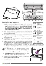
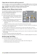
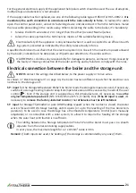
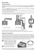
background image

Green Heating Technology

26

Inlet gas check

Remark:

 The pressure should be measured at nomi-

nal input, so this test must be performed with the 

burner ignited.

1. 

Loosen  (2-3  turns)  the  screw  of  pressure  tapping 

point for gas inlet 

2

 of the gas valve and insert the 

manometer sensor;

2. 

check  that  the  measured  pressure  complies  with 

the inlet gas nominal pressure (see "Technical data" 

on page 38).

3. 

close the pressure tapping point 

and 

check  the  

absence of gas leaks

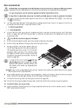
Max and Min pressure adjustment

1. 

Loosen  (2-3  turns)  the  screw  of  pressure  tapping 

point for gas outlet

 1

 of the gas valve and insert the 

manometer sensor. Leave the silicon tube (coming 

from the sealed chamber) inserted on the “Vent” 3;

2. 

Activate the boiler to its maximum output not mod-

ulated, using the “Chimney-sweeper” function. Proceed as follows:


• the boiler should be electrically powered and set in Heating Only mode. Use the button 

 if 

necessary;


• generate a heating request by activating the room thermostat;

  Be sure that the heat produced by the boiler can be eliminated by the heating system (through 

the radiators and/or radiant panels/floor systems).


• activate the boiler to its 

maximum output not modulated (Qn)

, using the “Chimney-sweeper” 

function, that activates by entering the technician menu and setting the parameter

 12

 to value

 1


(see also "PCB parameters settings (technician menu)" on page 27);

3.  wait at least 10 seconds

 and verify that the measured pressure corresponds to the MAX value 

indicated in the Technical data table > 

Gas supply pressure

 on page 39 or page 41, with regard 

to the boiler model and gas type;

4. 

extract one of the connectors

 4

 that supply the modulation coil; verify that the measured pres-

sure corresponds to the MIN value indicated in the Technical data table > 

Gas supply pressure

 on 

page 39 or page 41, with regard to the boiler model and gas type;

5. 

reinsert the connector

 4 

;

6. 

if it is necessary to adjust the regulation, proceed as it follows, referring to the figure:


• take off the protection cap

 C 


• adjust MAX pressure acting on the nut

 B

 (10 mm). Turn clockwise to increase pressure, counter-

clockwise to decrease pressure;


extract again one of the connectors

 4 

;


• adjust MIN pressure acting on the screw

 A

 (with a 4 mm screwdriver), paying attention not to 

contemporarily move the nut

 B 

. Turn clockwise to increase pressure, counterclockwise to de-

crease pressure;

Pressure tapping points:

outlet

inlet

equalization (VENT)

Содержание CITY GLASS 20 FR

Страница 1: ...CITY CLASS use installation adjustment maintenance Handbook instruction ENG 20 FR 25 FR 30 FR 35 FR Green Heating Technology ...

Страница 2: ... intake air 15 Domestic water supply characteristics 16 Protection against freezing 16 Outdoor installation in a partially protected place 16 Positioning and fastening 17 Hydraulic system DHW and heating 18 Advices and suggestions to avoid vibrations and noises in the system 18 Cleaning and preservation of the systems 18 Heating system 18 Piping between the boiler and the storage unit 19 Heating s...

Страница 3: ...d extra contractual responsibility for any damage arising from wrong installation wrong use and non observance of current laws and instructions given by the manufacturer himself f f Important this gas boiler is used to heat the water at a temperature lower than the boiling one at atmospheric pressure it must be connected to an heating system and or to a domestic hot water system in accordance with...

Страница 4: ...h them All the references to norms and national laws mentioned in this handbook are indicative as laws and norms are subject to issues and integrations by the authorities in charge Also comply to eventual local norms and laws not mentioned in this handbook in force in the territory where the installation takes place Personnel in charge of installation Always comply with national and or local regul...

Страница 5: ...alified technician and using original spare parts to operate with LPG G30 G31 The User must not touch sealed items nor break the seals Only specialized technicians and the official technical service can break the seals of sealed items The boiler is fitted with safety devices that block operation the case of problems with the boiler or related systems These devices must never be disabled if a devic...

Страница 6: ...on must be car ried out by qualified technicians in accordance with the Norms and Laws in force Maintenance operations must be carried out in compliance with the manufacturer prescriptions and in compliance with the laws and rules presently in force for what is not mentioned in this handbook we advice to perform them at least once a year to maintain the boiler s performance Appliance booklet or ce...

Страница 7: ...he storage tank RESET Press to reset the boiler in case of breakdown See further details in Alarms boiler block on page 32 Display symbols enabled in this model and their description CH winter mode indication If flashing it means that the boiler is functioning in CH mode See also the remark in the descrition of symbol Burner ON It indicates the presence of the flame in the burner DHW mode indicati...

Страница 8: ...rror mainly a fault that has to be managed by the Technician The User can anyway see Alarms boiler block on page 32 to get information about and the eventual actions to be carried out It informs that the outdoor probe accessories is installed Note In this case the CH system temperature is automatically set and so the use of the knob is different from the standard way for deeper details rely on kit...

Страница 9: ...s the temperature to which the water in the storage is heated If no temperature adjustment devices downstream the storage are installed the knob adjusts the temperature of the water to the user Otherwise this setting will affect only the maximum available temperature and on the duration of the availability of hot water in absence of heat input from external systems e g solar More complex systems c...

Страница 10: ...tion for what concerns the heating system temperature adjustment Note don t make confusion between the heating system temperature here described with the temperature of the room set on the Room Thermostat f f Heating system adjustment by using the knob the setting of the heating system temperature is made the value during the adjustment is shown on the display under the symbol Generally in the dee...

Страница 11: ...st ment on page 10 f f call a qualified technician to check gas valve regulation f f call a qualified technician to check and eventually clean the coil of the DHW storage Remark where the water hardness value is too high it is suggested the installation of a soften ing device in order to prevent the limestone precipitation this operation avoids a frequent cleaning of the coil of the DHW storage Bo...

Страница 12: ... rare cases of blockage due to inactivity in the presence of water and lime This can also occur when the boiler is locked red lamp on provided that the system pressure is correct In order for these systems to be active the boiler must be receiving gas and electricity boiler must be left on OFF mode shown on the display system pressure must be correct 1 1 5 bar in a cold state minimum 0 5 bar In ca...

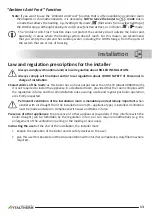
Страница 13: ...AFETY of Personnel in charge of installation Characteristics of the room as this boiler has an heat output lower than 35 kW about 30000 Kcal h it is not required to install the appliance in a dedicated room provided that the room complies with the regulation in force and that all installation rules assuring a safe and regular gas boiler operation are strictly respected Permanent ventilation of the...

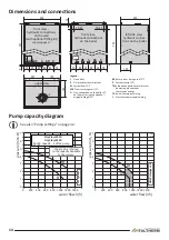
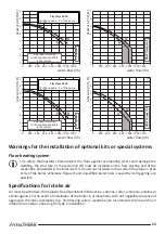
Страница 14: ...ply and room thermostat wirings TA Room thermostat wiring L Electrical power supply wiring front view hydraulic connections on the wall with optional fitting kit see also page 17 upper view front view hydraulic connections on the boiler left side view hydraulic connec tions on the boiler Pump capacity diagram See also Pump settings on page 32 0 1 2 3 4 5 6 7 0 200 400 1000 1200 600 800 1400 0 1 2 ...

Страница 15: ...he installation of optional kits or special systems Floor heating system The safety thermostat s that protects the floor against overheating that could damage the cladding the structure or the system itself must be installed on the flow starting end of the serpentine embedded in the floor itself It should not installed on the system flow pipe in prox imity of the boiler otherwise frequent and unju...

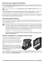
Страница 16: ...he storage unit and the relevant coil could be subject to freezing risk it is advisable to fill the heating circuit with instead of water an antifreeze liquid specific for heating systems propylenic gly col based following the instructions of its manufacturer Pay attention to the correct product concentration adding those substances to the heating water in incorrect dose could lead to the deformat...

Страница 17: ...rn storage coil flow and return gas and electrical cables predisposing them in the holes of the metal jig or as an alternative respecting the measures in the paragraph Dimensions and connections on page 14 The upper edge of boiler s body used as a reference in the paragraph Flue system types on page 23 is represented by the dotted line C in the figure If the Storage Unit is not installed in the sa...

Страница 18: ...of the systems against corrosions and there fore perforations noise leaks etc and limestone incrustations that drastically reduce the efficiency of the thermal exchange consider that 1 mm of limestone incrustations reduces of 18 the thermal exchange of the heating element on which it has been formed ITALTHERM guarantees its products only if the characteristics of the water comply with UNI 8065 re ...

Страница 19: ... and proceed depending on its type filling from aqueduct open it and let water flow in the system filling with anti freeze solution pump in the solution and pressurize the system f f Check the correct functioning of automatic venting devices eventually installed on the heating sys tem and or on the storage coil circuit f f Close the radiators venting devices as soon as water or anti freeze solutio...

Страница 20: ...e and ramp conformity with laws and rules currently in force internal and external tightness of the gas system and connections supply pipe must have a section greater than or equal to the boiler one supply gas must correspond to the one for which the boiler has been set otherwise it s manda tory to ask to qualified personnel to set the boiler for the correct gas type an interception valve must be ...

Страница 21: ...h the rules Electrical connection between the boiler and the storage unit NEVER connect the wirings described below to the power supply or to live wires As shown in Electrical diagram on page 44 the boiler has two different inputs for the electrical con nections to the storage unit SP input for the Storage temperature Probe the boiler reads the storage temperature and if necessary switches to stor...

Страница 22: ...NO YES Carefully follow the prescriptions by the National and Local Regulation in force Respect the minimum and maximum flue system length refer to Flue system types on page 23 Reducer for short systems In case of short air inlet and flue outlet systems to achieve the correct combustion the installation of a suitable flue diameter reducer could be necessary The reducer that fits most cases is supp...

Страница 23: ...equivalent length is 0 5m a 45 Ø80 bend equivalent length is 0 25m Note Split pipes allow to make also C12 and C32 flue systems Coaxial system C12 C32 1300 mm ø100 mm ø60 mm LCV ø125 mm 00010 00 LCO min 300 mm 130 mm ø100 90 mm ø60 00011 00 Model Coaxial system Ø60 100 mm LCO min max m LCV min max m Reducer LCO or LCV length m Ø mm 20 FR 25 FR 0 8 4 0 8 5 up to 1 43 F more than 1 NO 30 FR 0 8 3 0 ...

Страница 24: ...and tested Anyway it s advisable during the commissioning to check that the regulation is correct First starting up The first ignition operations consist in verifying the correct installation and functioning and in the even tual regulations which are necessary f f verify that the data of the plate correspond to those of the net supply electrical water gas f f verify the absence of the gas leakages...

Страница 25: ... minutes before performing combustion checks During this time the fumes of the eventual residual manufacturing materials are produced and they could alter the measured values f f verify the correct functioning of the boiler in heating and domestic hot water version f f fill in the foreseen documentation and leave to the user the copy of his competence Access to the inside of the boiler 1 Unscrew t...

Страница 26: ...floor systems activate the boiler to its maximum output not modulated Qn using the Chimney sweeper function that activates by entering the technician menu and setting the parameter 12 to value 1 see also PCB parameters settings technician menu on page 27 3 wait at least 10 seconds and verify that the measured pressure corresponds to the MAX value indicated in the Technical data table Gas supply pr...

Страница 27: ...setting of the parameter and you can set it by rotating the knob In case of PCB replacing check all of the parameter settings otherwise set them properly Please do not modify any firm setting if this is not required Main boiler parameters PC The parameters listed in the following table are limited to those described in this handbook The com plete parameter list is available in the documentation fo...

Страница 28: ...r models with flow meter instead of flow switch 1 fixed burner OFF at 75 C and burner ON at 65 C 2 linked to DHW SET Burner OFF when DHW temperature 3 C and burner ON when DHW temperature 2 C 12 0 2 0 Chimney sweeper function burner ignition not modulated to allow the combustion check For deeper details see paragraph Combustion test on page 29 0 burner off normal boiler work rimember to reset this...

Страница 29: ...d Then through a suitable function on the panel we ignite the burner at the maximum flow doing the measure and adjustments in this condition Proceed as follows 1 Prepare the instruments for combustion checking 2 activate the chimney sweeper function the boiler should be electrically powered and set in Heating Only mode Use the button if necessary generate a heating request by activating the room t...

Страница 30: ...he function in progress domestic hot water or heating Accessing the main board The main PCB has no hardware adjustment devic es onboard so no access to it is required except in case of cabling check or replacement of the board itself Proceed as follows Cut off the electrical supply to the boiler Restore the supply after having closed the control panel rear cover f f unscrew the screws 1 and releas...

Страница 31: ...on chamber 6 Remove the pipe between the gas valve and the injectors bar 7 Remove injectors bar 3 and replace the noz zles 5 see figure with the ones suitable for the available gas type using a 7 mm spanner possibly tube spanner The nozzles diam eter Ø is punched on each nozzle and should match the value stated in the table Technical data on page 38 Install all the new nozzles with the sup plied w...

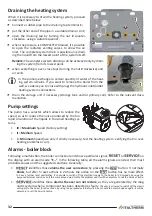
Страница 32: ...uce the speed so as to reduce the noise produced by the too rapid circulation of the liquids in too small heating sys tems III Maximum Speed Factory setting II Medium Speed I Minimum Speed use only if strictly necessary test the heating system verifying that no over heating problems occur Alarms boiler block Following a malfunction the boiler can lockout and show a particular signal or on the disp...

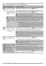
Страница 33: ...an be due in exam ple to combustion product reflow into intake duct leaks in intake outlet ducts or errors in sizing of ducts ducts length out of the allowed range and or wrong use of the reducer on boiler s outlet E02 the boiler has over heated and the Safety Thermostat has triggered Restore the boiler function by using the button If necessary wait at least 20 30 minutes to make the boiler cool a...

Страница 34: ... is factory preset see Electrical diagram on page 44 E17 Pushbutton failure The electronic has detected the actua tion of a pushbut ton for more than 30 seconds User check for jammed pushbuttons that remain pressed Discon nect the electrical supply to the boiler by operating the suitable external bipolar switch then connect it again after a few minutes Remove the main PCB and clean using suitable ...

Страница 35: ...f the probe is out of tolerance or in short circuit On the contrary if the probe or the relevant cabling is interrupted when the electrical supply is restored the boiler will consider the external probe absent and in Winter mode it will work in normal mode temperature shifting disabled E39 Suspected freezing After a power fail ure the boiler de tected tempera tures at the Heating and DHW probes eq...

Страница 36: ...nit f f Check the boiler ignition switching off and operation f f Check the water and gas connections tightness f f Check the gas consumption at the minimum and maximum output f f Verify that safety devices are correctly working f f Verify the correct functioning of control and adjusting devices f f Verify periodically the absence of leaks of combustion products to the inner room the correct func ...

Страница 37: ...Green Heating Technology 37 Notes ...

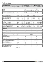
Страница 38: ... 3 CO at 0 O2 at Qn ppm 69 7 87 5 60 9 91 1 119 7 79 4 CO2 at nominal input 5 5 6 4 6 3 7 2 8 1 7 9 Flue temperature at Qn C 118 110 112 119 111 113 Flue mass flow rate at Qn kg h 53 74 53 62 54 22 51 93 53 21 53 82 Efficiency Nominal efficiency at Qn 92 7 93 3 Efficiency at 30 Qn 90 5 91 0 Heating Temperature selection range min max C 35 80 Expansion vessel l 8 8 Expansion vessel pre loading pres...

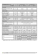
Страница 39: ... Connections Hydraulic and gas connections see Dimensions and connections on page 14 Flue types lengths and diameters see Flue systems on page 22 Gas supply pressure Nominal pressure mbar 20 37 20 37 Inlet pressure min max mbar 17 25 35 40 17 25 35 40 Injectors number 9 11 Injectors diameter mm 100 130 78 130 78 Gas pressure to injectors at Qn MAX mbar 12 4 27 8 35 7 13 0 27 5 35 6 Gas pressure to...

Страница 40: ...at 0 O2 at Qn ppm 84 8 103 7 61 3 85 2 102 5 76 9 CO2 at nominal input 7 5 8 4 8 0 6 9 7 9 7 7 Flue temperature at Qn C 122 121 120 118 123 122 Flue mass flow rate at Qn kg h 58 58 57 11 59 11 72 37 72 11 74 16 Efficiency Nominal efficiency at Qn 94 0 94 0 Efficiency at 30 Qn 91 5 92 0 Heating Temperature selection range min max C 35 80 Expansion vessel l 8 10 Expansion vessel pre loading pressure...

Страница 41: ... Connections Hydraulic and gas connections see Dimensions and connections on page 14 Flue types lengths and diameters see Flue systems on page 22 Gas supply pressure Nominal pressure mbar 20 37 20 37 Inlet pressure min max mbar 17 25 35 40 17 25 35 40 Injectors number 13 15 Injectors diameter mm 100 130 77 130 78 Gas pressure to injectors at Qn MAX mbar 12 8 27 7 35 8 12 6 27 4 35 4 Gas pressure t...

Страница 42: ... detection electrode 5 Safety thermostat on system flow 6 Temperature Sensor system flow 7 Motorized 3 way valve 8 Automatic Venting Device heating circuit incorporated in the pump 9 Safety valve 3 bar 10 Pump 11 Drain valve 12 Loss of water pressure switch 13 Gas valve 14 System pressure gauge 15 By pass in built in the 3 way valve hydraulic assembly 16 Burner 17 Primary exchanger 18 Sealed chamb...

Страница 43: ...tion electrode 5 Safety thermostat on system flow 6 Temperature Sensor system flow 7 Motorized 3 way valve 8 Automatic Venting Device heating circuit incorporated in the pump 9 Safety valve 3 bar 10 Pump 11 Drain valve 12 Loss of water pressure switch 13 Gas valve 14 System pressure gauge 15 By pass in built in the 3 way valve hydraulic assembly 16 Burner 17 Primary exchanger 18 Sealed chamber 19 ...

Страница 44: ...use F2A 2A fast 42 Resistor 2 2 kOhm 1 2W the contacts of these components are shown in standard conditions i e temperature below threshold cold system no system pressure no flow see Electrical connection between the boiler and the storage unit on page 21 for details Optional external devices SP DHW Storage temperature Probe ST DHW Storage Thermostat TA Room thermostat or Chronothermostat SELV sim...

Страница 45: ... Flue hood 3 Expansion vessel 5 Safety thermostat on system flow 6 Temperature Sensor system flow 7 Motorized 3 way valve 8 Automatic Venting Device heating circuit incorporated in the pump 9 Safety valve 3 bar 10 Pump 11 Drain valve 12 Loss of water pressure switch 13 Gas valve 14 System pressure gauge 15 By pass in built in the 3 way valve hydraulic assembly 16 Burner 17 Primary exchanger 18 Sea...

Страница 46: ...CH flow temperature as shown in the following graph 35 40 45 50 55 60 65 70 75 78 MAX MIN High temperature range 35 78 C 20 text C 15 10 5 0 5 10 15 20 25 27 20 25 30 35 40 45 MAX MIN Low temperature range 20 45 C if available kd 00 kd 05 kd 01 kd 10 kd 15 kd 20 kd 25 kd 30 00177 ENG 00 Practically kd value should be adjusted depending on the estimated efficiency of the building s ther mal insulat...

Страница 47: ...ould be kept separated from power supply cables e g by enclosing it into separate raceways The maximum overall cable length shouldn t exceed 50 m 1 Cut off electricity from boiler 2 install the device as described in the paragraph 1 of the supplied instruction booklet 3 connect the terminals OT nr 1 2 of the Remote Control to the TA Room Thermostat Remote Control cable coming out of the boiler by ...

Страница 48: ...Green Heating Technology 48 Notes ...

Страница 49: ...Green Heating Technology 49 Notes ...

Страница 50: ...ts products the company has the right to change features and data written in the present manual at any time and without notice 960000134_02 20190107 ITALTHERM Srl Via S D Acquisto 10 29010 Pontenure PC IT Tel 39 0523 575611 Fax 39 0523 575600 www italtherm it e mail info italtherm it www italtherm it Green Heating Technology UNI EN ISO 9001 2015 ...

Отзывы: