Green Heating Technology
45
Hydraulic diagram
This
diag
ram
is
for
in
forma
tion
only
.
To mak
e
boil
-
er
hy
dr
aulic
connection
either
see
"Dimensions
and
con
nections"
on
pag
e
14
and
ev
en
tually
"P
ositioning and f
as
tening" on pag
e
17.
00384 00
M
R
M RB
MB
G
3
14
16
17
18
19
15
7
9
11
10
8
13
7
6
5
2
1
1
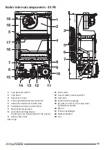
Flue pressure switch
2
Flue hood
3
Expansion vessel
5
Safety thermostat on system flow
6
Temperature Sensor, system flow
7
Motorized 3-way valve
8
Automatic Venting Device
(heating circuit, incorporated in the pump)
9
Safety valve 3 bar
10
Pump
11
Drain valve
12
Loss of water pressure switch
13
Gas valve
14
System pressure gauge
15
By-pass (in-built in the 3-way valve hydraulic
assembly)
16
Burner
17
Primary exchanger
18
Sealed chamber
19
Fan
R
Heating return
M
Heating flow
RB
Return from storage coil
MB
Flow to storage coil
G
Gas inlet
Содержание CITY GLASS 20 FR
Страница 37: ...Green Heating Technology 37 Notes ...
Страница 48: ...Green Heating Technology 48 Notes ...
Страница 49: ...Green Heating Technology 49 Notes ...

