


Operation Manual of INVT CHS100 AC Servo Drive 6 Detailed parameter description
88
torque command signal. Its input has directionality. We can adjust the corresponding
relationship between the AI voltage and torque command by setting this group of
parameters to meet the requirements of different applications. In the speed mode, it is
used as torque limit signal. Its absolute value is used to limit the positive/negative
torque (i.e. the absolute value of the actual torque is limited below this value).
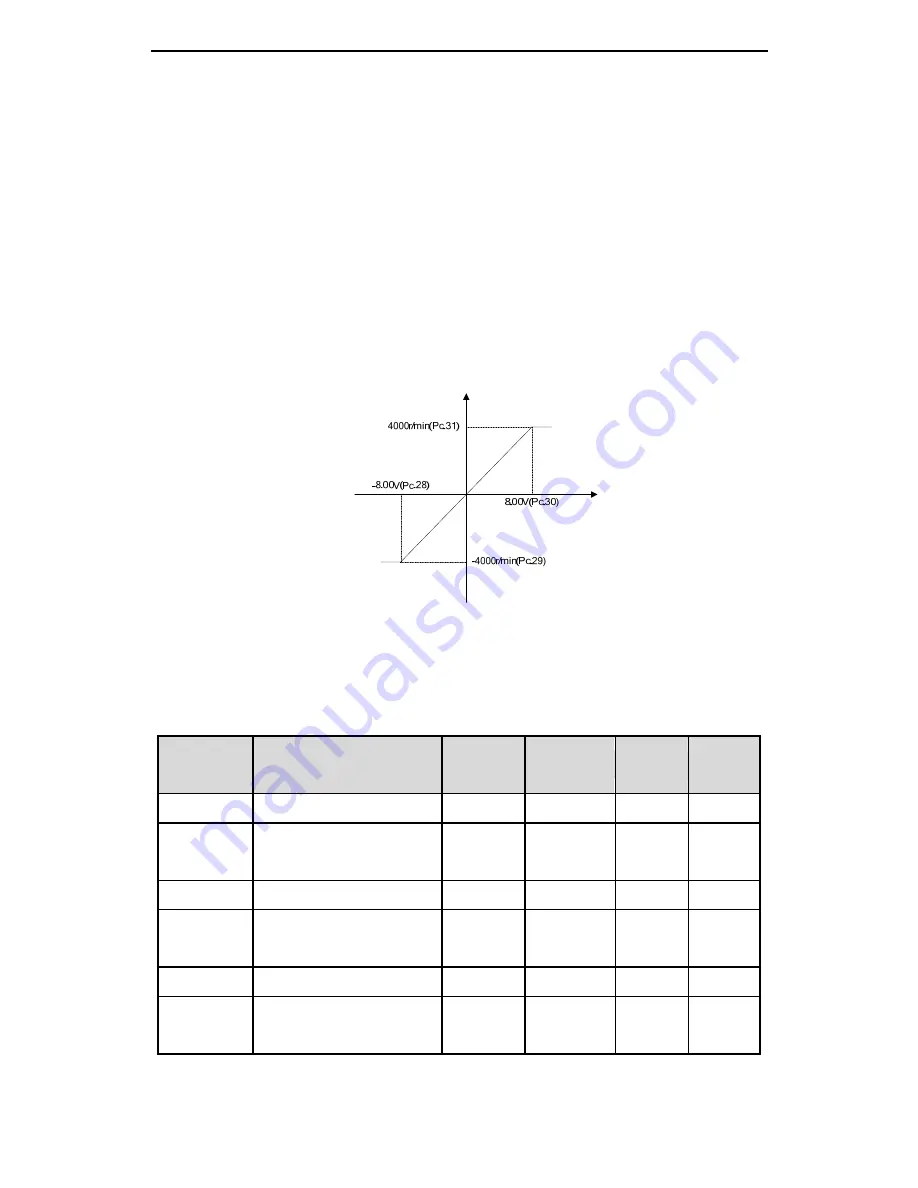
Take a 1.5kW servo drive as an example. The motor speed is controlled by analog
input. It is required that ±8V correspond to ±4000r/min. We set Pc.28=-8.00,
Pc.30=8.00. Pc.29=-4000, Pc.31=4000. The relationship between the actual speed
setting and the input voltage is shown in the figure as below:
Fig. 6-12 Schematic diagram of AI setting
The defaults of the corresponding settings of the lower limit and upper limit of AI 1 are
related to the power level of the drive: higher than 1.0kW (inclusive) are -2500 and
2500, less than 1.0kW are -5000 and 5000.
Function
code
Name
Unit
Range
Default
Mode
Pc.36
Voltage lower limit of AO 1
V
0.00~10.00
0.00
P.S.T
Pc.37
Corresponding setting of
lower limit of AO 1
% 0.0~100.0
0.0 P.S.T
Pc.38
Voltage upper limit of AO 1
V
0.00~10.00
10.00
P.S.T
Pc.39
Corresponding setting of
upper limit of AO 1
% 0.0~100.0
100.0
P.S.T
Pc.40
Voltage lower limit of AO 2
V
0.00~10.00
0.00
P.S.T
Pc.41
Corresponding setting of
lower limit of AO 2
% 0.0~100.0
0.0 P.S.T
Speed
Voltage