


Operation Manual of INVT CHS100 AC Servo Drive 6 Detailed parameter description
61
position mode, it can control the angular displacement of the servo motor with the pulse
command and thus achieve the goal to control the displacement of the mechanical
movement.
1: Speed mode
The standard wiring diagram for the speed mode is shown in chapter 5.1.1.2. In the
speed mode, it can control the rotation speed of the servo motor with the internal speed
command or external analog speed command.
2: Torque mode
The standard wiring diagram for the torque mode is shown in chapter 5.1.1.3. In the
torque mode, it can control the output torque of the servo motor with the internal torque
command or external analog torque command.
3: Position/speed mode
In this mode, you can switch between the position mode and speed mode with the
control mode switching terminal (MCH). The corresponding relationships of the
terminal status and modes are:
MCH
Control mode
0 Position
mode
1 Speed
mode
0
:
OFF (the terminal is disconnected with COM-);
1
:
ON (the terminal is connected with COM-).
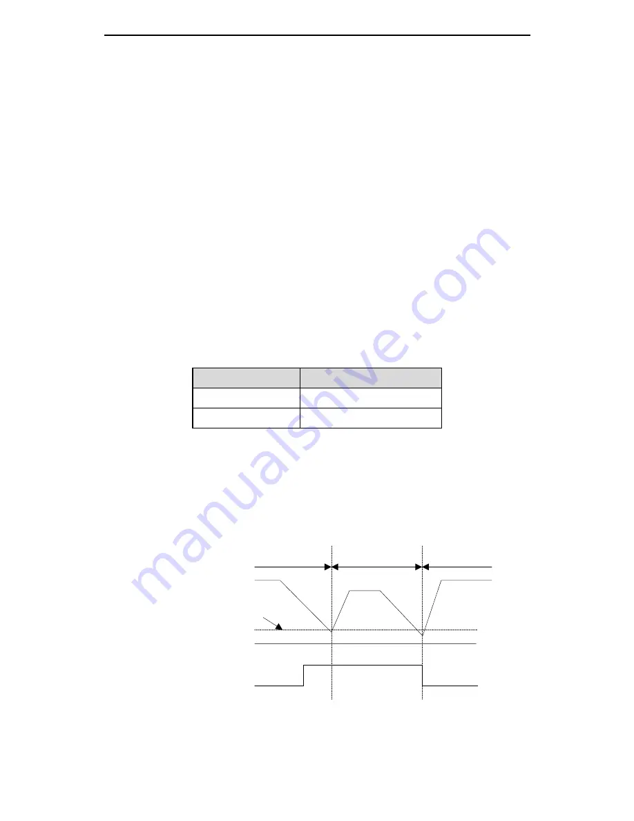
For safety, after changing the MCH terminal input status, the switching between
position mode and speed mode can be performed only when the motor speed
becomes lower than the value of zero speed range (PC.05). The switching process is
shown in the figure below:
ON
OFF
Fig. 6-1 Schematic diagram of position/speed mode switching
4: Speed/torque mode
Position mode
Speed mode
Position mode
Zero speed
threshold (set with
PC.05)
Motor speed
Mode switching
signal (MCH)