


Operation Manual of INVT CHS100 AC Servo Drive 4 Signal and wiring
22
4.5 I/O signal wiring (CN1 connector)
4.5.1 Overview
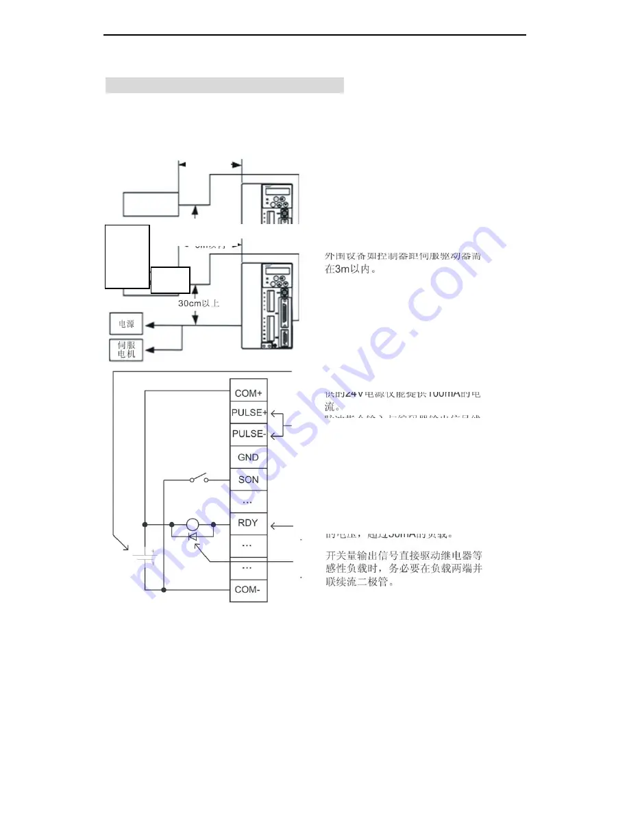
Fig. 4-7 I/O signal wiring diagram
Controller
Power
supply
Servo
drive
Within 3m
30cm or more
The peripheral equipment such as the
controller must be within 3m from the
servo drive.
The control cable must be kept at least
30cm away from the power cable and
motor cable. Do not bind them together
or lay them in one cable ducts.
The user is recommended to prepare the
12-24V DC power supply of 500mA or
more capacity used for the control signal.
The local 24V power supply of the drive
can only provide 100mA current.
The signal wires for pulse command
input and encoder output should adopt
shielded twisted pair.
Do not apply a voltage higher than 30V
or a load over 50mA on the digital output
terminal.
The digital output signals drives inductive
loads directly such as relay, etc. Be sure
to fit a freewheeling diode on each end of
the load.