


Operation Manual of INVT CHS100 AC Servo Drive 5 Running and operation
41
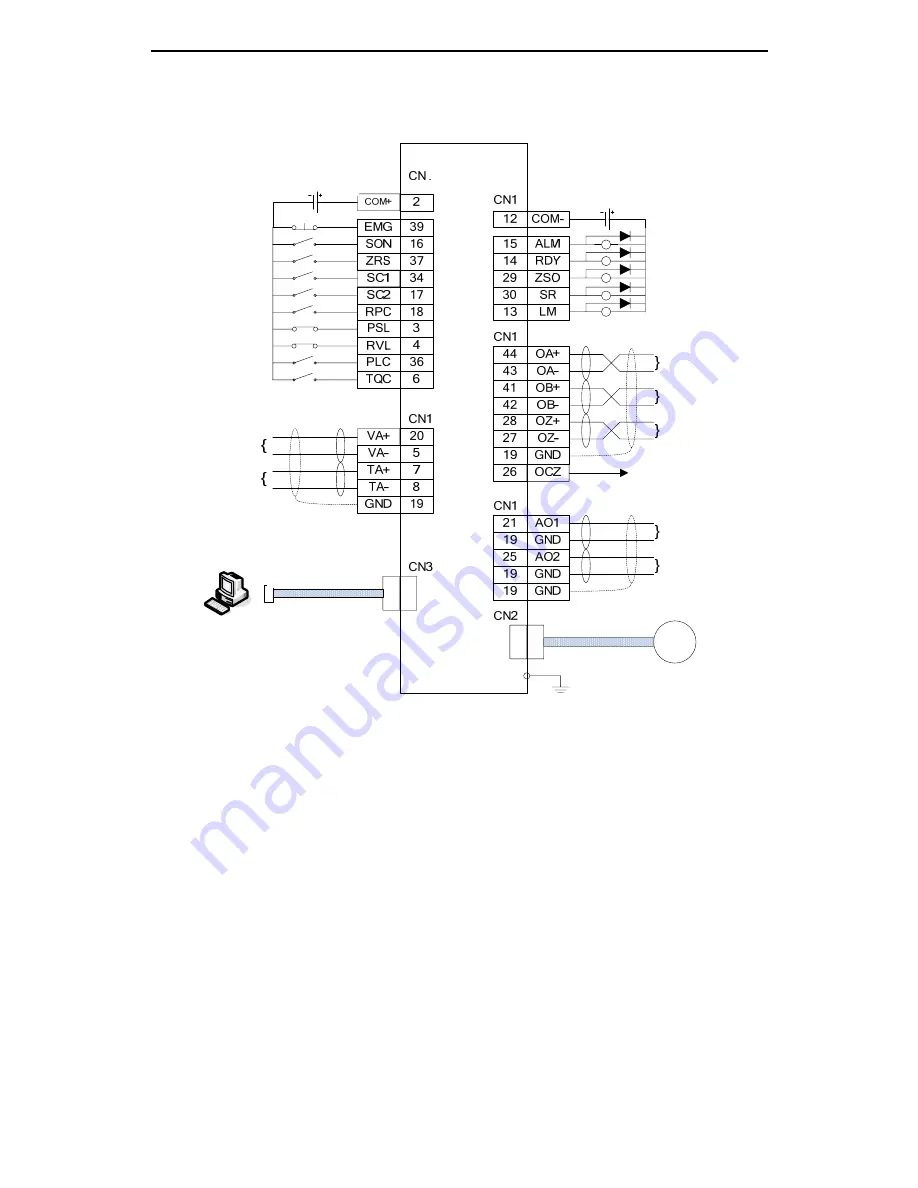
5.1.1.2 Standard wiring diagram for the speed mode
Fig. 5-2 Wiring diagram for the speed mode
Notes:
The pulse input can be either differential mode or open-collector mode. For
detailed wiring instruction, please refer to chapter 4.5.3. To avoid
interference to the input pulse, be sure to ground the drive reliably.
The analog input power supply is provided externally. For detailed wiring
instruction, please refer to chapter 4.5.4.
The digital input can use internal 24V power supply. At this time, connect
the 24V to COM+ and the other end of the switch to COM-. For detailed
wiring instruction, please refer to chapter 4.5.2.
Be sure to connect the diode with correct polarity. Otherwise the protection
circuit may not be work normally. If the internal 24V power supply is used,
the sum of the external relays current should be less than 100mA. For
Servo drive
Note 3
Note 4
Note 2
Fault alarm (Note 5)
Servo ready
Zero speed
Position reaching
Torque limiting
Encoder phase A
output
Encoder phase B
output
Encoder phase Z
output
Open-collector
output of phase Z
pulse
Analog output 1
Analog output 2
Encoder cable
Motor
Emergency stop
Servo enabling
Zero speed clamp
Speed selection 1
Speed selection 2
FWD/REV selection
Forward travel limit
Reverse travel limit
Gain switching
Torque limit selection
Analog quantity of
speed reference
Analog quantity of
torque limitation
Communication cable