


Operation Manual of INVT CHS100 AC Servo Drive 5 Running and operation
49
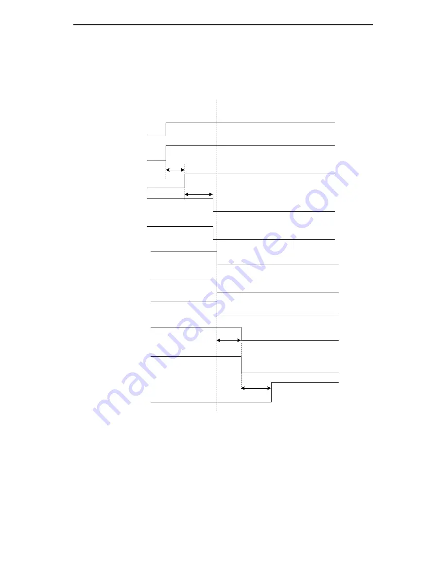
5.1.8 Sequence diagram
5.1.8.1 Sequence diagram of power-on and servo ON
50m
s
200ms
200ms
100m
s
Fig. 5-4 Sequence diagram of Power-on and servo ON
Power-on process
Servo on process
Main power supply
Control power supply
CPU reset level
Servo fault (ALM) output
Servo ready
(RDY) output
Servo enabling
(SON)
Dynamic brake signal
Fan signal
PWM output
Electromagnetic
brake signal
Position/speed/torque
command input
Main circuit
powered on
Control circuit
powered on
Program starts
running
No fault alarm
Note 1
Note 2
Dynamic braking relay closed (note 3)
Fan is running
Servo has output
Motor releases the brake
Command input is valid.
Fan does not run
Servo has no output
Motor brakes
Command input is invalid
Note 1: The conditions for the servo ready (RDY) output signal level to become low is the servo with no fault
and the bus voltage has been built up (bus voltage is higher than 220V). There will be AL-PoF warning
when the bus voltage is below 220V;
Note 2: The servo enabling signal is invalid only when the servo ready (RDY) output signal is low level;
Note 3: The drives below 400W (inclusive) have no dynamic brake. But they provide dynamic braking functions.
Approx.200ms