


Operation Manual of INVT CHS100 AC Servo Drive 5 Running and operation
50
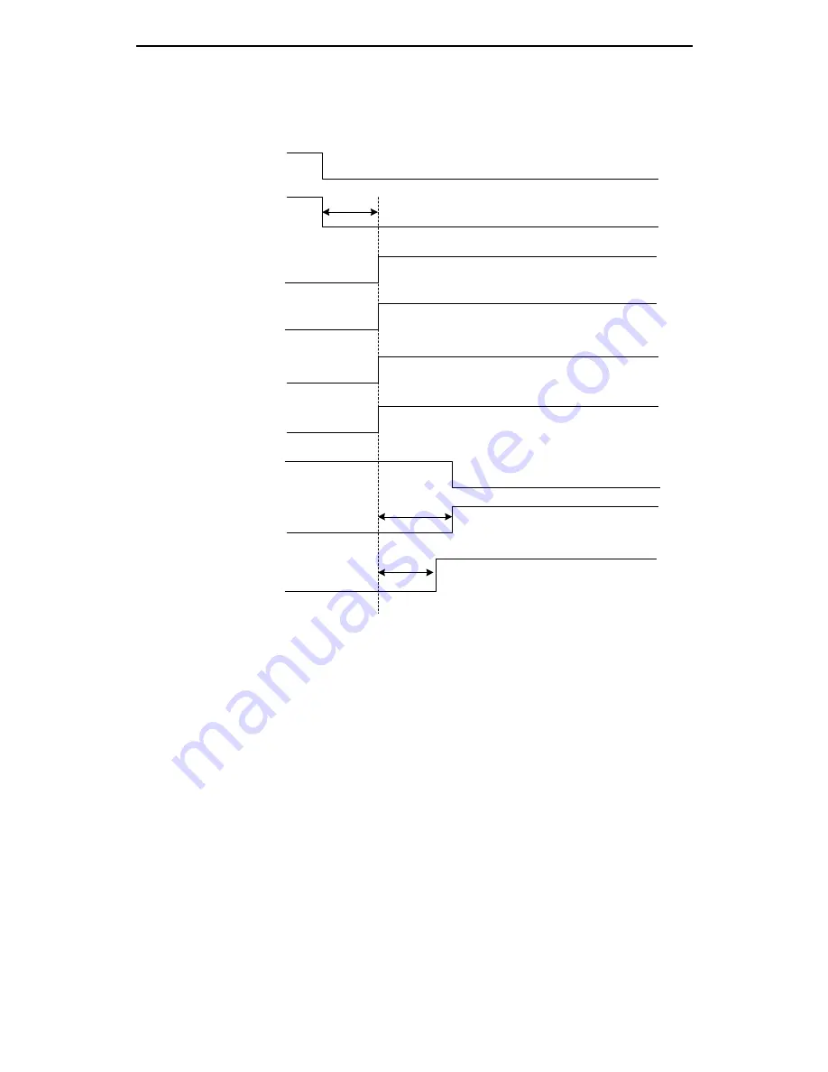
5.1.8.2 Sequence diagram of power loss during running
Fig. 5-5 Sequence diagram of power loss during running
Main circuit power loss
Control circuit power fail
Fault alarm
Servo has output
Servo has no output
Note 1
Dynamic braking relay disconnected (note 3)
Note 2
Note 4
Note 5
Program stops running
Fan stops running
Motor brakes
Fan is running
Motor releases
the brake
Main power supply
Control power supply
Servo fault (ALM)
output
PWM output
Servo ready
(RDY) output
Dynamic brake signal
CPU reset level
Fan signal
Electromagnetic brake
signal (BRK) output
Note 1: When the bus voltage of the control circuit drops below 200V, an undervoltage fault will occur. At this time the
servo fault (ALM) output becomes high level;
Note 2: Pc.52 can set the function of immediate disconnection of the dynamic braking relay at undervoltage fault
Note 3: The drives below 400W (inclusive) have no dynamic brake. But they provide dynamic braking functions;
Note 4: When the module temperature is less than 45
℃
, the fan will stop. If the module temperature is higher than
45
℃
, the fan stops running after the CPU reset level becomes lower;
Note 5: The output delay time of the electromagnetic brake signal can be set by the function code Pc.51.At the same
time, if the speed drops below 30r/min within the time set of Pc.51, the electromagnetic brake signal (BRK) will
also become stronger.