


CAMERAS FRAME GRABBERS IMAGING SOLUTIONS
BOBCAT Hardware User’s Manual
IMPERX
Rev. 2.0.9
6421 Congress Ave.
4/8/2014
Boca Raton, FL 33487
www.imperx.com
+1 (561) 989-0006
62 of 329
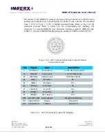
1.4.3 GigE (GEV) Camera Output
The interface between the GEV camera and outside equipment is done via 3
connectors and one LED, located on the back panel of the camera – Figure 1.6.
1.
Camera output – standard RJ-45 provides data, sync, control, and serial interface.
2.
Male 12-pin Power Connector – provides power and I/O interface.
3.
Female 12-pin Connector – provides RS232 serial control interface, Lens
Control signals for Zoom, Focus, and Iris for a standard Type 1 (6V) or Type 5
(12V) C-Mount motorized lens.
4.
USB type B programming/SPI connector.
5.
Status LED – indicates the status of the camera – refer to Status LED ion.
6.
Serial Number – shows camera model and serial number.
Figure 1.6 – GEV Camera back panel – GigE output
The Camera’s video data output along with the serial communication and triggering
signals are serialized and continuously transmitted over the Gigabit Ethernet
interface at GigE’s full 1-Gb/s line rate, while delivering consistently low,
predictable latencies. The network interface is compatible with IP/Ethernet networks
operating at 1000 Mb/s using standard LAN CAT-5 (CAT-5e) cables.
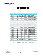
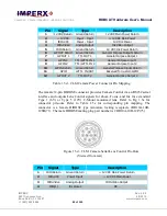
The male 12-pin Hirose connector provides power and all external input/output
signals supplied to the camera. Refer to Fig 1.6a for connector pin-outs. Refer to
Table 1.6a for corresponding pin mapping. The connector is a male HIROSE type
miniature locking receptacle #HR10A-10R-12PB(71). The power supply is shipped
with a power cable which terminates in a female HIROSE plug #HR10A-10P-
12S(73), and has two small BNC pig-tail cables for the external trigger input (black)


