


CAMERAS FRAME GRABBERS IMAGING SOLUTIONS
BOBCAT Hardware User’s Manual
IMPERX
Rev. 2.0.9
6421 Congress Ave.
4/8/2014
Boca Raton, FL 33487
www.imperx.com
+1 (561) 989-0006
49 of 329
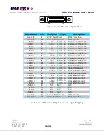
1.3 CAMERA CONNECTIVITY
1.4.1 CLB (Base) - Camera Link (CL) Output
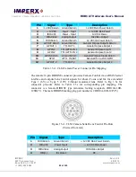
The interface between the BOBCAT-CLB cameras and outside equipment is done
via 4 connectors and one LED, located on the back panel of the camera – Figure 1.4.
1.
One Camera outputs – standard Base Camera Link Mini provides data, sync,
control, serial interface and PoCL power.
2.
Male 12-pin Power Connector – provides power and I/O interface.
3.
Female 12-pin I/O interface with Lens Control outputs
4.
USB type B programming/SPI connector.
5.
Status LED – indicates the status of the camera – refer to Status LED section.
6.
Serial Number – shows camera model and serial number.
Figure 1.4 – CLB Camera back panel – Base Camera Link output
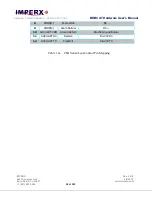
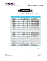
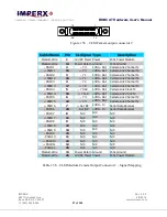
The Camera’s video data output is compliant with Base Camera Link standard and
includes 12VDC Power over camera Link (PoCL), 4 W max, 24 data bits, 4 sync
signals (LVAL, FVAL, DVAL and User Out), 1 reference clock, 2 external inputs
CC1, CC2 and a bi-directional serial interface. The camera link output connector is
shown in Figure 1.4a, and the corresponding signal mapping in Table 1.4a.


