CAMERAS FRAME GRABBERS IMAGING SOLUTIONS
BOBCAT Hardware User’s Manual
IMPERX
Rev. 2.0.9
6421 Congress Ave.
4/8/2014
Boca Raton, FL 33487
www.imperx.com
+1 (561) 989-0006
59 of 329
Port
Port/bit
8-bits
Tap 1, 2
10-bits
Tap 1, 2
12-bits
Tap 1, 2
DATA 38
Port E6
N/C
C6
C6
DATA 39
Port E7
N/C
C7
C7
DATA 40
Port F0
N/C
C8
C8
DATA 41
Port F1
N/C
C9
C9
DATA 42
Port F2
N/C
N/C
C10
DATA 43
Port F3
N/C
N/C
C11
DATA 44
Port F4
N/C
D8
D8
DATA 45
Port F5
N/C
D9
D9
DATA 46
Port F6
N/C
N/C
F10
DATA 47
Port F7
N/C
N/C
D11
ENABLE 0
LVAL
LVAL
LVAL
LVAL
ENABLE 1
FVAL
FVAL
FVAL
FVAL
ENABLE 2
DVAL
DVAL
DVAL
DVAL
ENABLE 3
User Out
User Out
User Out
User Out
CONTROL 0
CC 1
CC 1
CC 1
CC 1
CONTROL 1
CC 2
CC 2
CC 2
CC 2
CONTROL 2
N/C
N/C
N/C
N/C
CONTROL 3
N/C
N/C
N/C
N/C
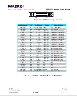
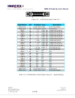
Table 1.5c – Medium Camera Link bit assignment
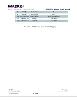
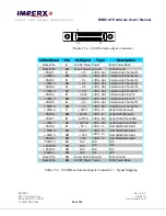
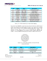
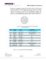
The power and all external input/output signals are supplied to the camera via the
camera power connector shown in Figure 1.5c. The corresponding pin mapping is
shown in Table 1.5d. The connector is a male HIROSE type miniature locking
receptacle #HR10A-10R-12PB(71).
Figure 1.5c – CLB Camera Power Connector
(Viewed from rear)


