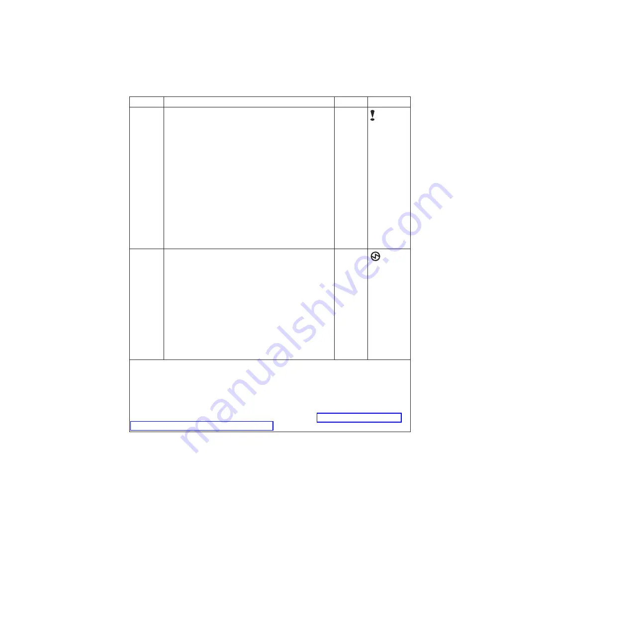
Table 13. Node canister LEDs (continued)
Name
Description
Color
Symbol
Fault
Indicates if a fault is present and identifies which
canister.
v
The on status indicates that the node is in service
state or an error exists that might be stopping the
software from starting. Do not assume that this
status indicates a hardware error. Further
investigation is required before replacing the node
canister.
v
The off status indicates that the node is a candidate
or is active. This status does not mean that there is
not a hardware error on the node. Any error that
was detected is not severe enough to stop the node
from participating in a system.
v
The flashing status indicates that the canister is
being identified. This status might or might not be
a fault.
Amber
Power
Indicates if power is available and the boot status of
the canister.
v
The on status indicates that the canister is powered
on and that the main processor or processors are
running.
v
The off status indicates that no power is available.
v
The slow flashing (1 Hz) status indicates that power
is available and that the canister is in standby
mode. The main processor or processors are off and
only the service processor is active.
v
The fast flashing (2 Hz) indicates that the canister is
running the power-on self-test (POST).
Green
Notes:
1.
If the system status LED is on and the fault LED is off, the node canister is an active
member of a system.
2.
If the system status LED is on and the fault LED is on, there is a problem establishing a
system.
For a more complete identification of the system LEDs, go to “Procedure: Understanding
the system status using the LEDs” on page 49.
Expansion canister ports and indicators
An expansion canister is one of two canisters that is located in the rear of the
expansion enclosure. The expansion canister has no controls.
There is a diagnostic port on the left of the canister. There are no indicators that
are associated with the port. There are no defined procedures that use the port.
Note:
The reference to the left and right locations applies to canister 1, which is
the upper canister. The port locations are inverted for canister 2, which is the lower
canister.
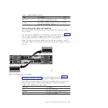
Expansion canister SAS ports and indicators
Two SAS ports are located in the rear of the expansion canister.
Chapter 1. Storwize V7000 hardware components
15
Содержание Storwize V7000
Страница 1: ...IBM Storwize V7000 Version 6 3 0 Troubleshooting Recovery and Maintenance Guide GC27 2291 02...
Страница 6: ...vi Storwize V7000 Troubleshooting Recovery and Maintenance Guide...
Страница 8: ...viii Storwize V7000 Troubleshooting Recovery and Maintenance Guide...
Страница 10: ...x Storwize V7000 Troubleshooting Recovery and Maintenance Guide...
Страница 34: ...18 Storwize V7000 Troubleshooting Recovery and Maintenance Guide...
Страница 42: ...26 Storwize V7000 Troubleshooting Recovery and Maintenance Guide...
Страница 80: ...64 Storwize V7000 Troubleshooting Recovery and Maintenance Guide...
Страница 128: ...112 Storwize V7000 Troubleshooting Recovery and Maintenance Guide...
Страница 156: ...140 Storwize V7000 Troubleshooting Recovery and Maintenance Guide...
Страница 166: ...150 Storwize V7000 Troubleshooting Recovery and Maintenance Guide...
Страница 171: ......
Страница 172: ...Printed in USA GC27 2291 02...


