Enclosure end cap indicators
This topic describes the indicators on the enclosure end cap.
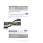
Figure 5 shows where the end caps are located on the front of an enclosure with 12
drives. The end caps are located in the same position for an enclosure with 24
drives.
v
1
Left end cap
v
2
Drives
v
3
Right end cap
Figure 6 shows the indicators on the front of the enclosure end cap.
The left enclosure end caps for both enclosures are identical and contain only
indicators. The left enclosure end cap contains no controls or connectors. The right
enclosure end cap for both enclosures has no controls, indicators, or connectors.
svc00694
1
2
3
Figure 5. 12 drives and two end caps
2
3
1
4
svc00605
Figure 6. Left enclosure end cap
4
Storwize V7000: Troubleshooting, Recovery, and Maintenance Guide
Содержание Storwize V7000
Страница 1: ...IBM Storwize V7000 Version 6 3 0 Troubleshooting Recovery and Maintenance Guide GC27 2291 02...
Страница 6: ...vi Storwize V7000 Troubleshooting Recovery and Maintenance Guide...
Страница 8: ...viii Storwize V7000 Troubleshooting Recovery and Maintenance Guide...
Страница 10: ...x Storwize V7000 Troubleshooting Recovery and Maintenance Guide...
Страница 34: ...18 Storwize V7000 Troubleshooting Recovery and Maintenance Guide...
Страница 42: ...26 Storwize V7000 Troubleshooting Recovery and Maintenance Guide...
Страница 80: ...64 Storwize V7000 Troubleshooting Recovery and Maintenance Guide...
Страница 128: ...112 Storwize V7000 Troubleshooting Recovery and Maintenance Guide...
Страница 156: ...140 Storwize V7000 Troubleshooting Recovery and Maintenance Guide...
Страница 166: ...150 Storwize V7000 Troubleshooting Recovery and Maintenance Guide...
Страница 171: ......
Страница 172: ...Printed in USA GC27 2291 02...

