Working with Memory-Module Kits
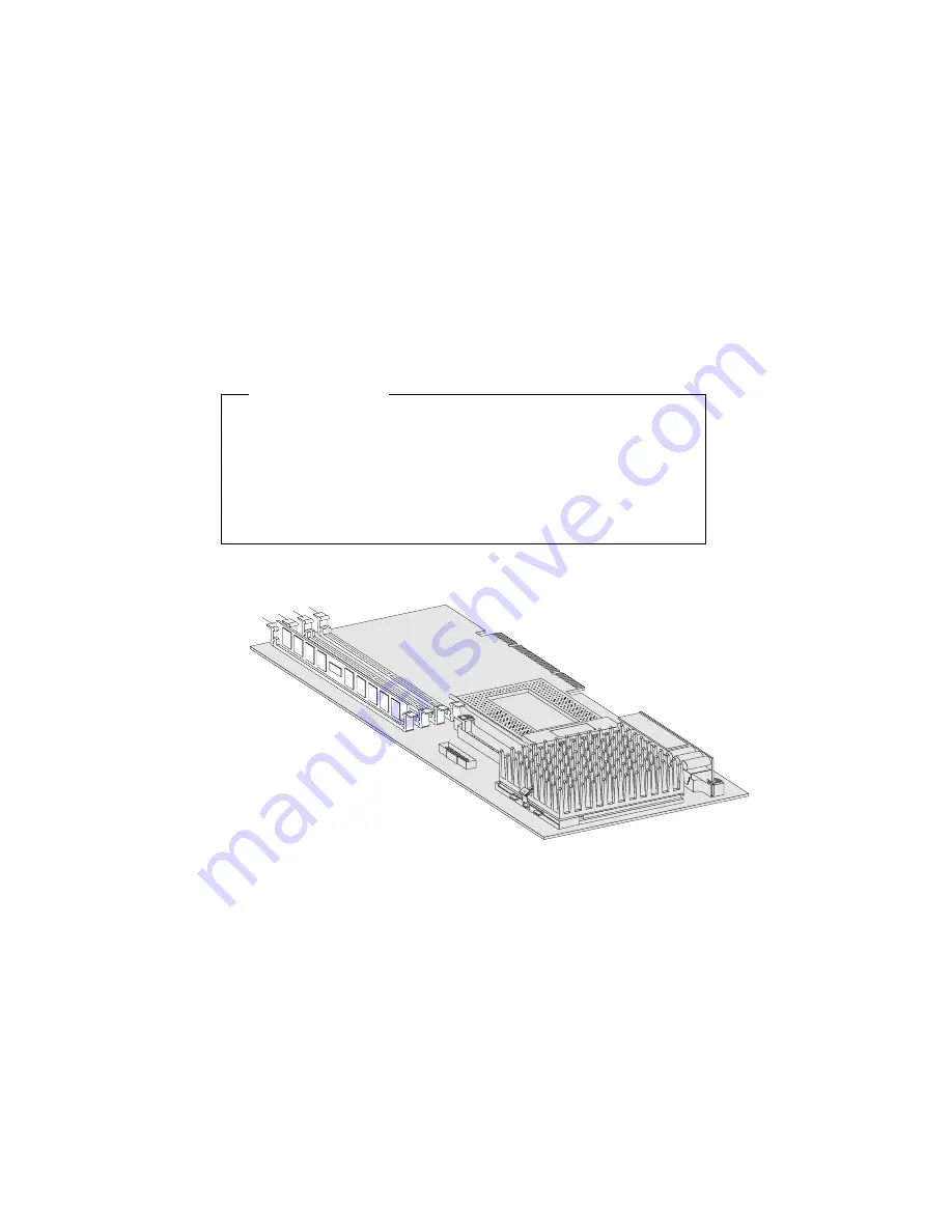
Installing Memory-Module Kits
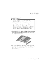
Before you begin
Read “Electrical Safety” on page 53 and “Handling
Static-Sensitive Devices” on page 54.
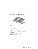
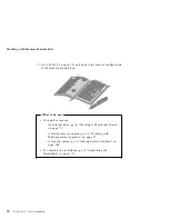
Turn off the server.
Disconnect all external cables and power cords, and then
remove the server cover (see “Preparing to Add Options” on
page 55).
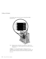
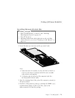
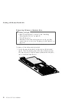
1. Locate the memory connectors on the processor board.
J2 J3
J4 J5
Notes:
a. Each connector slot contains two keys (dividers), which are
used to assure that a memory-module kit can be installed
only in the correct position.
b. A retaining clip at each end of the connector locks the
memory-module kit into place.
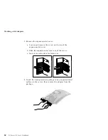
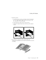
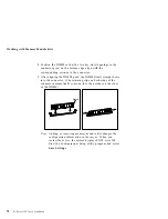
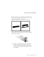
2. Press the retaining clips at the ends of the connector outward, to
the open position.
3. Touch the static-protective package containing the DIMM to any
unpainted metal surface on the server; then, remove the
memory-module kit from the package.
Chapter 3. Installing Options
71
Содержание PC Server 325
Страница 1: ...PC Server 325 User s Handbook IBM...
Страница 6: ...vi PC Server 325 User s Handbook...
Страница 10: ...Laser Compliance Statement x PC Server 325 User s Handbook...
Страница 136: ...Updating the Server Configuration 122 PC Server 325 User s Handbook...
Страница 212: ...Resolving Configuration Conflicts 198 PC Server 325 User s Handbook...
Страница 238: ...Installed Device Records 224 PC Server 325 User s Handbook...
Страница 287: ......
Страница 288: ...IBM Part Number 76H8831 Printed in U S A September 1996 76H8831...

