Working with Microprocessor Upgrades
.1/
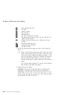
Heat sink retention clip
.2/
Fan sink
.3/
Heater spreader
.4/
Pin 1 location
.5/
Microprocessor
.6/
Fan power cable connector (J21)
.7/
Secondary microprocessor socket, empty, with lever in
closed, locked position
.8/
Primary processor board socket, with latch in closed
position
.9/
Secondary VRM connector
.1ð/
Voltage regulator module
.11/
Fan power cable
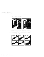
1. Locate the secondary microprocessor socket on the processor
board.
Note: When you install a microprocessor that is the same clock
speed as the microprocessor that comes with your server,
you do not need to change any jumper positions. If you
install microprocessors that have a different clock speed
from the one that comes with your server, you must
change microprocessor jumper positions on the processor
board.
See “Processor Board Jumpers” on page 214 for detailed
information on the jumper positions.
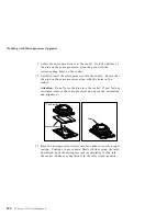
2. Lift the latch on the socket.
Attention
: The pins on the microprocessor are delicate and
susceptible to damage from static electricity and physical
mishandling. Do not touch or bend the exposed pins. Protect
the pins while carrying the microprocessor and while installing
the microprocessor and the fan sink.
100
PC Server 325 User's Handbook
Содержание PC Server 325
Страница 1: ...PC Server 325 User s Handbook IBM...
Страница 6: ...vi PC Server 325 User s Handbook...
Страница 10: ...Laser Compliance Statement x PC Server 325 User s Handbook...
Страница 136: ...Updating the Server Configuration 122 PC Server 325 User s Handbook...
Страница 212: ...Resolving Configuration Conflicts 198 PC Server 325 User s Handbook...
Страница 238: ...Installed Device Records 224 PC Server 325 User s Handbook...
Страница 287: ......
Страница 288: ...IBM Part Number 76H8831 Printed in U S A September 1996 76H8831...

