


Drive Logic Card—How it works
The drive logic card, located in each drive pack, basically consists of a data path and a control path. The
data path receives data from the SCSI bus, then buffers it, checks it for parity and CRC, compacts it,
re-buffers it, formats it to fit the 3570 data format, and sends it to the drive analog card, and ultimately to
the head-actuator assembly to be written to the media. In read-back, it receives read data pulses from the
drive analog card, clocks them, de-skews them, corrects parallel data, buffers it, de-compacts it, and
transfers the data to the SCSI bus.
The drive logic card contains the main microprocessor, the microcode load, clock generation circuits, reset
controls, and control registers that interface with all other drive electrical/mechanical components.
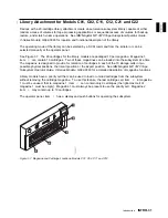
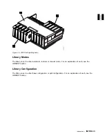
Library Models:
The drive logic card controls the motion of the accessor assembly and the picker
assembly by sending commands to these devices through the library control card which performs as the
library interface. The drive logic card also monitors tach pulses from the motors, and sense data from the
various library sensors through the library control card interface.
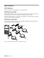
Host Communications:
The drive logic card serves as the primary SCSI interface for the device
through a SCSI adapter and on-board SCSI drivers. All host communications to the 3570 go through the
drive logic card via this interface. SCSI commands are received, and routed under microcode control
throughout the device. SCSI data is received and sent as discussed earlier.
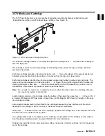
The SCSI ID switch is located on the drive logic card and is used to set the SCSI address for drive-only
installations. The SCSI ID switch is not used on library models. The SCSI address on library models is
set from the library operator panel display.
Microcode:
Microcode, which is housed on the drive logic card, handles data and commands from the
SCSI bus, and transfers data and controls the drive analog card, drive servo card, the loader assembly,
head-actuator assembly, and the library components. During read from the media, the microcode controls
the receiving and buffering of data from the drive logic card, and controls the actuator location in relation
to the media. The microcode also provides communication to the operator or CE by communicating
through the drive LEDs, the library operator panel display, and library LEDs. Bring-up diagnostics perform
initialization and testing during Power On, and collects and presents error or ATTENTION data when
intervention is required. Each installed drive contains microcode.
Data Handling:
The drive logic card controls special compaction hardware to compact data before
sending it out to be written to the tape media. During a tape read operation, data that is received from the
R/W head is first corrected for skew, then is un-compacted and buffered for further transmission over the
SCSI bus.
Sense Gathering:
Sensing devices located in the drive pack send sense data through the drive
servo card to the drive logic card. Sensing devices located in the library area send sense data through
the library control card to the drive logic card.
Drive Logic Card to Drive Analog Card Interface:
Most clocking for the 3570 is generated
by the drive logic card. It operates at 40Mhz or clocks derived from this frequency. The microprocessor
resident on the drive logic card runs at 20Mhz. The only off card use for drive logic card clock circuitry is
a 20Mhz signal sent to the drive analog card during write operations and during transfer of LWR (Loop
Write to Read) data. The library control card contains its own clock controls. During a write operation the
drive logic card sends equalized write data and clock pulses to the drive analog card. During transfer of
LWR data, the drive logic card clocks the LWR data from the drive analog card. The data is buffered and
checked in both directions to ensure data integrity.
INTRO
Introduction
INTRO-19
Содержание Magstar MP 3570 C Series
Страница 1: ...IBM Magstar MP 3570 Tape Subsystem Maintenance Information C Series Models...
Страница 2: ......
Страница 12: ...x IBM 3570 MI...
Страница 46: ...MAPS 2 IBM 3570 MI...
Страница 56: ...Notes MAPS 12 IBM 3570 MI...
Страница 62: ...MAPS 18 IBM 3570 MI...
Страница 70: ...Notes MAPS 26 IBM 3570 MI...
Страница 72: ...MAPS 28 IBM 3570 MI...
Страница 84: ...Figure 22 Label Locations for Models Without Libraries INTRO 12 IBM 3570 MI...
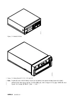
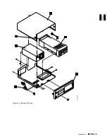
Страница 87: ...Figure 25 Model C00 Drive INTRO Introduction INTRO 15...
Страница 95: ...Figure 29 Model C02 Stand Alone Library Model INTRO Introduction INTRO 23...
Страница 96: ...A 2 1 M 0 0 3 5 Figure 30 Model C11 Rack Mounted Library Model INTRO 24 IBM 3570 MI...
Страница 97: ...Figure 31 Model C12 Rack Mounted Library Model INTRO Introduction INTRO 25...
Страница 98: ...Figure 32 Model C21 Rack Mounted Library Model INTRO 26 IBM 3570 MI...
Страница 99: ...Figure 33 Model C22 Rack Mounted Library Model INTRO Introduction INTRO 27...
Страница 120: ...INTRO 48 IBM 3570 MI...
Страница 124: ...Figure 51 3570 Cartridge Magazine Figure 52 3570 Cartridge Magazine Lock Lever LIBRARY 4 IBM 3570 MI...
Страница 136: ...Figure 57 Model C02 Stand Alone Library Model LIBRARY 16 IBM 3570 MI...
Страница 137: ...A 2 1 M 0 0 3 5 Figure 58 Model C11 Rack Mounted Library Model LIBRARY Library LIBRARY 17...
Страница 138: ...Figure 59 Model C12 Rack Mounted Library Model LIBRARY 18 IBM 3570 MI...
Страница 139: ...Figure 60 Model C21 Rack Mounted Library Model LIBRARY Library LIBRARY 19...
Страница 144: ...LIBRARY 24 IBM 3570 MI...
Страница 192: ...Figure 108 Operator Menus PANEL 12 IBM 3570 MI...
Страница 206: ...Figure 128 Part 1 of 3 CE Panel Menu PANEL 26 IBM 3570 MI...
Страница 207: ...Figure 128 Part 2 of 3 CE Panel Menu PANEL Operator Panel PANEL 27...
Страница 208: ...Figure 128 Part 3 of 3 CE Panel Menu PANEL 28 IBM 3570 MI...
Страница 242: ...PANEL 62 IBM 3570 MI...
Страница 249: ...Korean Inspection INSP 7...
Страница 250: ...Korean INSP 8 IBM 3570 MI...
Страница 256: ...Figure 187 Support Slide left side Models C21 and C22 INSP 14 IBM 3570 MI...
Страница 260: ...INSP 18 IBM 3570 MI...
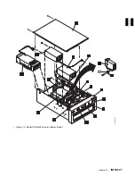
Страница 270: ...Figure 196 Model C00 Drive Inner Cover Configuration INST 10 IBM 3570 MI...
Страница 273: ...Figure 200 Drive Only Model C00 SCSI Connection INST Installation INST 13...
Страница 275: ...Figure 202 EIA Rack Template for Models C11 and C12 INST Installation INST 15...
Страница 276: ...This Page Left Intentionally Blank INST 16 IBM 3570 MI...
Страница 288: ...INST 28 IBM 3570 MI...
Страница 289: ...Figure 212 EIA Rack Template for Models C21 and C22 INST Installation INST 29...
Страница 290: ...This Page Left Intentionally Blank INST 30 IBM 3570 MI...
Страница 297: ...Figure 216 Attaching Cable Arm and Strain Relief Bracket INST Installation INST 37...
Страница 312: ...Figure 227 Rear View of Model C02 C12 or C22 INST 52 IBM 3570 MI...
Страница 319: ...Figure 237 Cable Routing Model C11 INST Installation INST 59...
Страница 320: ...Figure 238 Cable Routing Model C12 Figure 239 Cable length adjusting Models C11 and C12 INST 60 IBM 3570 MI...
Страница 321: ...Figure 240 Cable Routing Model C21 INST Installation INST 61...
Страница 322: ...Figure 241 Cable Routing Model C22 Figure 242 Cable length adjusting Models C21 and C22 INST 62 IBM 3570 MI...
Страница 328: ...INST 68 IBM 3570 MI...
Страница 345: ...Figure 251 Loading a Cartridge in a Magazine with Operator Side Facing Down PROC Common Procedures PROC 17...
Страница 348: ...Figure 252 Removing a Stuck Cartridge From a Drive PROC 20 IBM 3570 MI...
Страница 349: ...Figure 253 Drive Front View Unloaded Figure 254 Drive Front View Loaded PROC Common Procedures PROC 21...
Страница 369: ...Figure 260 Blank Error Log Analysis Work Sheet PROC Common Procedures PROC 41...
Страница 371: ...Figure 263 Example Error Log Analysis Work Sheet PROC Common Procedures PROC 43...
Страница 396: ...6 When the Tape Device Test menu is displayed select Exit test menu 3 PROC 68 IBM 3570 MI...
Страница 420: ...PROC 92 IBM 3570 MI...
Страница 424: ...Figure 270 Library Model C01 Exploded View CARR 4 IBM 3570 MI...
Страница 435: ...Figure 274 Base Drive FRU Breakout CARR Checks Adjustments Removals and Replacements CARR 15...
Страница 448: ...Figure 279 Library Front Door Assembly Holding Screws CARR 28 IBM 3570 MI...
Страница 456: ...CARR 36 IBM 3570 MI...
Страница 504: ...APPENDC 2 IBM 3570 MI...
Страница 521: ...APPENDC Appendix C APPENDC 19...
Страница 522: ...Notes APPENDC 20 IBM 3570 MI...
Страница 532: ...APPENDC 30 IBM 3570 MI...
Страница 537: ...Figure 312 Library Model C01 Exploded View APPENDD Appendix D APPENDD 5...
Страница 541: ...Figure 315 Basic Drive All Models APPENDD Appendix D APPENDD 9...
Страница 546: ...Figure 317 Base Drive FRU Breakout APPENDD 14 IBM 3570 MI...
Страница 551: ...Figure 318 Base Drive Head Actuator Assembly Close up APPENDD Appendix D APPENDD 19...
Страница 556: ...Head Actuator Cable Holding Tool Template This page left intentionally blank APPENDD 24 IBM 3570 MI...
Страница 557: ...APPENDD Appendix D APPENDD 25...
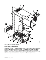
Страница 563: ...Figure 326 Drive Loader Assembly Exploded View APPENDD Appendix D APPENDD 31...
Страница 580: ...Figure 332 Library Front Door Assembly Holding Screws APPENDD 48 IBM 3570 MI...
Страница 591: ...Parts Catalog Parts Catalog PARTS 3...
Страница 592: ...Assembly 1 Rackmount Library Assembly Model C11 PARTS 4 IBM 3570 MI...
Страница 594: ...Assembly 2 Desktop Drive Model C00 PARTS 6 IBM 3570 MI...
Страница 596: ...Assembly 3 Desktop Library Assembly Model C01 PARTS 8 IBM 3570 MI...
Страница 598: ...Assembly 4 Rackmount Library Assembly Model C12 PARTS 10 IBM 3570 MI...
Страница 601: ...Parts Catalog Parts Catalog PARTS 13...
Страница 602: ...Assembly 5 Desktop Library Assembly Model C02 PARTS 14 IBM 3570 MI...
Страница 605: ...Parts Catalog Parts Catalog PARTS 17...
Страница 606: ...Assembly 6 Rackmount Library Assembly Model C21 PARTS 18 IBM 3570 MI...
Страница 608: ...Assembly 7 Rackmount Library Assembly Model C22 PARTS 20 IBM 3570 MI...
Страница 611: ...Parts Catalog Parts Catalog PARTS 23...
Страница 612: ...Assembly 8 Base Drive All Models PARTS 24 IBM 3570 MI...
Страница 614: ...PARTS 26 IBM 3570 MI...
Страница 629: ...wrap tool SCSI port PROC 77 INDEX Index Index 7...


