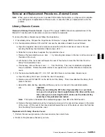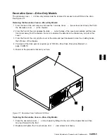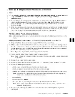
|
Removal and Replacement Procedures—Drive Pack
|
Notes:
|
1. This procedure applies only to Non EMEA countries and regions that support the Drive Pack as a
|
single FRU. EMEA countries should be using the procedures at “Appendix D” on
|
page APPENDD-1.
|
2. Be sure that you are working on a C—Series drive. C—Series drives have green UNLOAD buttons
|
and are at microcode level D1I5_xxx or higher. If your drive has a blue UNLOAD button, or is at
|
microcode level D1I4_xxx, refer to
Magstar MP 3570 Tape Subsystem Maintenance Information
|
B—Series Models.
|
3. When you are removing the drive pack, you may want to complete your testing prior to replacement of
|
the covers. For testing purposes, you can feed cartridges in a drive-only device, without having all the
|
covers back on, if you connect all the cables and place the drive on a flat surface.
FID B3—Drive Pack, Library Models
Note: After replacing a drive pack, you must update the microcode to the latest level on all drives in the
device.
Removal of Drive Pack from Chassis: To remove the physical drive follow the steps below:
1. “Prepare the Tape Device for Service” on page PROC-5 and then return here.
|
2. If this is a drive in a Model C02, C12, or C22, when the new drive is installed, if it is at a higher level
|
than the other drive in the device, you will be asked to update the other drive to the level of microcode
|
that the new drive is at. If the other drive is at a higher level than the new drive, you will be updating
|
the new drive to the same level as the other drive.
|
Note: If you have any questions, call the support center for advice.
3. Perform removal of the “Library Chassis Covers” on page CARR-3.
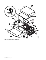
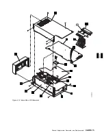
Note: Refer to Figure 270 on page CARR-4 for a view of the drive pack within a typical library model
environment.
|
4. Remove the ac power cord to power supply
|
5. Remove the 4 screws that hold the rear plate, item
15
to the library frame and remove the plate.
|
6. Remove the following from the drive:
|
a. 4-wire power connection between the drive and power supply
|
b. 2-wire fan power connection between the drive and power supply
|
c. Ribbon cable (Library Interface/RS-422) from the library control card (library models, drive 1 only)
|
Note: To remove the cable connector from the drive and control card connectors, depress the
|
tension clips on either side of the cable connectors.
|
d. SCSI cable(s)
|
e. SCSI terminator if installed
|
f. The RS-422 cable connecting drive 1 to drive 2 (Models C02, C12 and C22 only)
|
Note: Remove the stand-offs that hold the RS-422 cable to the drive frame, and set the cable
|
assembly aside for now.
|
7. Refer to Figure 270 on page CARR-4 for a view of the drive pack within a typical library model
|
environment.
CARR
Checks, Adjustments, Removals, and Replacements
CARR-7
Содержание Magstar MP 3570 C Series
Страница 1: ...IBM Magstar MP 3570 Tape Subsystem Maintenance Information C Series Models...
Страница 2: ......
Страница 12: ...x IBM 3570 MI...
Страница 46: ...MAPS 2 IBM 3570 MI...
Страница 56: ...Notes MAPS 12 IBM 3570 MI...
Страница 62: ...MAPS 18 IBM 3570 MI...
Страница 70: ...Notes MAPS 26 IBM 3570 MI...
Страница 72: ...MAPS 28 IBM 3570 MI...
Страница 84: ...Figure 22 Label Locations for Models Without Libraries INTRO 12 IBM 3570 MI...
Страница 87: ...Figure 25 Model C00 Drive INTRO Introduction INTRO 15...
Страница 95: ...Figure 29 Model C02 Stand Alone Library Model INTRO Introduction INTRO 23...
Страница 96: ...A 2 1 M 0 0 3 5 Figure 30 Model C11 Rack Mounted Library Model INTRO 24 IBM 3570 MI...
Страница 97: ...Figure 31 Model C12 Rack Mounted Library Model INTRO Introduction INTRO 25...
Страница 98: ...Figure 32 Model C21 Rack Mounted Library Model INTRO 26 IBM 3570 MI...
Страница 99: ...Figure 33 Model C22 Rack Mounted Library Model INTRO Introduction INTRO 27...
Страница 120: ...INTRO 48 IBM 3570 MI...
Страница 124: ...Figure 51 3570 Cartridge Magazine Figure 52 3570 Cartridge Magazine Lock Lever LIBRARY 4 IBM 3570 MI...
Страница 136: ...Figure 57 Model C02 Stand Alone Library Model LIBRARY 16 IBM 3570 MI...
Страница 137: ...A 2 1 M 0 0 3 5 Figure 58 Model C11 Rack Mounted Library Model LIBRARY Library LIBRARY 17...
Страница 138: ...Figure 59 Model C12 Rack Mounted Library Model LIBRARY 18 IBM 3570 MI...
Страница 139: ...Figure 60 Model C21 Rack Mounted Library Model LIBRARY Library LIBRARY 19...
Страница 144: ...LIBRARY 24 IBM 3570 MI...
Страница 192: ...Figure 108 Operator Menus PANEL 12 IBM 3570 MI...
Страница 206: ...Figure 128 Part 1 of 3 CE Panel Menu PANEL 26 IBM 3570 MI...
Страница 207: ...Figure 128 Part 2 of 3 CE Panel Menu PANEL Operator Panel PANEL 27...
Страница 208: ...Figure 128 Part 3 of 3 CE Panel Menu PANEL 28 IBM 3570 MI...
Страница 242: ...PANEL 62 IBM 3570 MI...
Страница 249: ...Korean Inspection INSP 7...
Страница 250: ...Korean INSP 8 IBM 3570 MI...
Страница 256: ...Figure 187 Support Slide left side Models C21 and C22 INSP 14 IBM 3570 MI...
Страница 260: ...INSP 18 IBM 3570 MI...
Страница 270: ...Figure 196 Model C00 Drive Inner Cover Configuration INST 10 IBM 3570 MI...
Страница 273: ...Figure 200 Drive Only Model C00 SCSI Connection INST Installation INST 13...
Страница 275: ...Figure 202 EIA Rack Template for Models C11 and C12 INST Installation INST 15...
Страница 276: ...This Page Left Intentionally Blank INST 16 IBM 3570 MI...
Страница 288: ...INST 28 IBM 3570 MI...
Страница 289: ...Figure 212 EIA Rack Template for Models C21 and C22 INST Installation INST 29...
Страница 290: ...This Page Left Intentionally Blank INST 30 IBM 3570 MI...
Страница 297: ...Figure 216 Attaching Cable Arm and Strain Relief Bracket INST Installation INST 37...
Страница 312: ...Figure 227 Rear View of Model C02 C12 or C22 INST 52 IBM 3570 MI...
Страница 319: ...Figure 237 Cable Routing Model C11 INST Installation INST 59...
Страница 320: ...Figure 238 Cable Routing Model C12 Figure 239 Cable length adjusting Models C11 and C12 INST 60 IBM 3570 MI...
Страница 321: ...Figure 240 Cable Routing Model C21 INST Installation INST 61...
Страница 322: ...Figure 241 Cable Routing Model C22 Figure 242 Cable length adjusting Models C21 and C22 INST 62 IBM 3570 MI...
Страница 328: ...INST 68 IBM 3570 MI...
Страница 345: ...Figure 251 Loading a Cartridge in a Magazine with Operator Side Facing Down PROC Common Procedures PROC 17...
Страница 348: ...Figure 252 Removing a Stuck Cartridge From a Drive PROC 20 IBM 3570 MI...
Страница 349: ...Figure 253 Drive Front View Unloaded Figure 254 Drive Front View Loaded PROC Common Procedures PROC 21...
Страница 369: ...Figure 260 Blank Error Log Analysis Work Sheet PROC Common Procedures PROC 41...
Страница 371: ...Figure 263 Example Error Log Analysis Work Sheet PROC Common Procedures PROC 43...
Страница 396: ...6 When the Tape Device Test menu is displayed select Exit test menu 3 PROC 68 IBM 3570 MI...
Страница 420: ...PROC 92 IBM 3570 MI...
Страница 424: ...Figure 270 Library Model C01 Exploded View CARR 4 IBM 3570 MI...
Страница 435: ...Figure 274 Base Drive FRU Breakout CARR Checks Adjustments Removals and Replacements CARR 15...
Страница 448: ...Figure 279 Library Front Door Assembly Holding Screws CARR 28 IBM 3570 MI...
Страница 456: ...CARR 36 IBM 3570 MI...
Страница 504: ...APPENDC 2 IBM 3570 MI...
Страница 521: ...APPENDC Appendix C APPENDC 19...
Страница 522: ...Notes APPENDC 20 IBM 3570 MI...
Страница 532: ...APPENDC 30 IBM 3570 MI...
Страница 537: ...Figure 312 Library Model C01 Exploded View APPENDD Appendix D APPENDD 5...
Страница 541: ...Figure 315 Basic Drive All Models APPENDD Appendix D APPENDD 9...
Страница 546: ...Figure 317 Base Drive FRU Breakout APPENDD 14 IBM 3570 MI...
Страница 551: ...Figure 318 Base Drive Head Actuator Assembly Close up APPENDD Appendix D APPENDD 19...
Страница 556: ...Head Actuator Cable Holding Tool Template This page left intentionally blank APPENDD 24 IBM 3570 MI...
Страница 557: ...APPENDD Appendix D APPENDD 25...
Страница 563: ...Figure 326 Drive Loader Assembly Exploded View APPENDD Appendix D APPENDD 31...
Страница 580: ...Figure 332 Library Front Door Assembly Holding Screws APPENDD 48 IBM 3570 MI...
Страница 591: ...Parts Catalog Parts Catalog PARTS 3...
Страница 592: ...Assembly 1 Rackmount Library Assembly Model C11 PARTS 4 IBM 3570 MI...
Страница 594: ...Assembly 2 Desktop Drive Model C00 PARTS 6 IBM 3570 MI...
Страница 596: ...Assembly 3 Desktop Library Assembly Model C01 PARTS 8 IBM 3570 MI...
Страница 598: ...Assembly 4 Rackmount Library Assembly Model C12 PARTS 10 IBM 3570 MI...
Страница 601: ...Parts Catalog Parts Catalog PARTS 13...
Страница 602: ...Assembly 5 Desktop Library Assembly Model C02 PARTS 14 IBM 3570 MI...
Страница 605: ...Parts Catalog Parts Catalog PARTS 17...
Страница 606: ...Assembly 6 Rackmount Library Assembly Model C21 PARTS 18 IBM 3570 MI...
Страница 608: ...Assembly 7 Rackmount Library Assembly Model C22 PARTS 20 IBM 3570 MI...
Страница 611: ...Parts Catalog Parts Catalog PARTS 23...
Страница 612: ...Assembly 8 Base Drive All Models PARTS 24 IBM 3570 MI...
Страница 614: ...PARTS 26 IBM 3570 MI...
Страница 629: ...wrap tool SCSI port PROC 77 INDEX Index Index 7...


