equipment check. An asynchronous indication of a
malfunction.
EREP. Environmental recording, editing, and printing.
Error log. A dataset or file in a product or system
where error information is stored for later access.
ESD. Electrostatic discharge.
F
fault symptom code (FSC). A hexadecimal code
generated by the drive or the control unit microcode in
response to a detected subsystem error.
FC. Feature code.
FCC. Federal communications commission.
FE. Field engineer, customer engineer, or service
representative.
FID. FRU identifier (may be more than one FRU). For
additional information, see “FID Entry Point” on
page START-12.
field replaceable unit (FRU). An assembly that is
replaced in its entirety when any one of its components
fails.
FID entry point. A place in the START section that
lists all the FID numbers and suggested directions to
the service representative to accomplish a repair.
file. A named set of records stored or processed as a
unit. Also referred to as a dataset.
file protection. The processes and procedures
established in an information system that are designed
to inhibit unauthorized access to, contamination of, or
deletion of a file.
FLASH EEPROM. An electrically erasable
programmable read-only memory (EEPROM) that can
be updated.
FMR. Field microcode replacement.
format. The arrangement or layout of data on a data
medium.
formatter. Part of a magnetic tape subsystem that
performs data conversion, speed matching, encoding,
first level error recovery, and interfaces to one or more
tape drives.
FP. File protect.
frayed. Damaged as if by an abrasive substance.
FRU. Field replaceable unit.
FSC. Fault symptom code.
FSI. Fault symptom index.
functional microcode. Microcode that is resident in
the machine during normal customer operation.
G
g. Gram.
gnd. Ground.
H
hertz (Hz). Unit of frequency. One hertz equals one
cycle per second.
hex. Hexadecimal.
Hz. Hertz (cycles per second).
I
ID. Identifier.
identifier (ID). (1) In programming languages, a
lexical unit that names a language object; for example,
the names of variables, arrays, records, labels, or
procedures. An identifier usually consists of a letter
optionally followed by letters, digits, or other characters.
(2) One or more characters used to identify or name
data element and possibly to indicate certain properties
of that data element. (3) A sequence of bits or
characters that identifies a program, device, or system
to another program, device, or system.
IDRC. Improved Data Recording Capability.
IML. Initial microprogram load.
Improved Data Recording Format. An improved data
recording mode that can increase the effective data
capacity and the effective data rate when enabled and
invoked.
initial microprogram load (IML). The action of
loading a microprogram from an external storage to
writable control storage.
initiator. The component that executes a command.
The initiator can be the host system or the tape control
unit.
INST. Installation.
GLOSSARY
Glossary
Gloss-3
Содержание Magstar MP 3570 C Series
Страница 1: ...IBM Magstar MP 3570 Tape Subsystem Maintenance Information C Series Models...
Страница 2: ......
Страница 12: ...x IBM 3570 MI...
Страница 46: ...MAPS 2 IBM 3570 MI...
Страница 56: ...Notes MAPS 12 IBM 3570 MI...
Страница 62: ...MAPS 18 IBM 3570 MI...
Страница 70: ...Notes MAPS 26 IBM 3570 MI...
Страница 72: ...MAPS 28 IBM 3570 MI...
Страница 84: ...Figure 22 Label Locations for Models Without Libraries INTRO 12 IBM 3570 MI...
Страница 87: ...Figure 25 Model C00 Drive INTRO Introduction INTRO 15...
Страница 95: ...Figure 29 Model C02 Stand Alone Library Model INTRO Introduction INTRO 23...
Страница 96: ...A 2 1 M 0 0 3 5 Figure 30 Model C11 Rack Mounted Library Model INTRO 24 IBM 3570 MI...
Страница 97: ...Figure 31 Model C12 Rack Mounted Library Model INTRO Introduction INTRO 25...
Страница 98: ...Figure 32 Model C21 Rack Mounted Library Model INTRO 26 IBM 3570 MI...
Страница 99: ...Figure 33 Model C22 Rack Mounted Library Model INTRO Introduction INTRO 27...
Страница 120: ...INTRO 48 IBM 3570 MI...
Страница 124: ...Figure 51 3570 Cartridge Magazine Figure 52 3570 Cartridge Magazine Lock Lever LIBRARY 4 IBM 3570 MI...
Страница 136: ...Figure 57 Model C02 Stand Alone Library Model LIBRARY 16 IBM 3570 MI...
Страница 137: ...A 2 1 M 0 0 3 5 Figure 58 Model C11 Rack Mounted Library Model LIBRARY Library LIBRARY 17...
Страница 138: ...Figure 59 Model C12 Rack Mounted Library Model LIBRARY 18 IBM 3570 MI...
Страница 139: ...Figure 60 Model C21 Rack Mounted Library Model LIBRARY Library LIBRARY 19...
Страница 144: ...LIBRARY 24 IBM 3570 MI...
Страница 192: ...Figure 108 Operator Menus PANEL 12 IBM 3570 MI...
Страница 206: ...Figure 128 Part 1 of 3 CE Panel Menu PANEL 26 IBM 3570 MI...
Страница 207: ...Figure 128 Part 2 of 3 CE Panel Menu PANEL Operator Panel PANEL 27...
Страница 208: ...Figure 128 Part 3 of 3 CE Panel Menu PANEL 28 IBM 3570 MI...
Страница 242: ...PANEL 62 IBM 3570 MI...
Страница 249: ...Korean Inspection INSP 7...
Страница 250: ...Korean INSP 8 IBM 3570 MI...
Страница 256: ...Figure 187 Support Slide left side Models C21 and C22 INSP 14 IBM 3570 MI...
Страница 260: ...INSP 18 IBM 3570 MI...
Страница 270: ...Figure 196 Model C00 Drive Inner Cover Configuration INST 10 IBM 3570 MI...
Страница 273: ...Figure 200 Drive Only Model C00 SCSI Connection INST Installation INST 13...
Страница 275: ...Figure 202 EIA Rack Template for Models C11 and C12 INST Installation INST 15...
Страница 276: ...This Page Left Intentionally Blank INST 16 IBM 3570 MI...
Страница 288: ...INST 28 IBM 3570 MI...
Страница 289: ...Figure 212 EIA Rack Template for Models C21 and C22 INST Installation INST 29...
Страница 290: ...This Page Left Intentionally Blank INST 30 IBM 3570 MI...
Страница 297: ...Figure 216 Attaching Cable Arm and Strain Relief Bracket INST Installation INST 37...
Страница 312: ...Figure 227 Rear View of Model C02 C12 or C22 INST 52 IBM 3570 MI...
Страница 319: ...Figure 237 Cable Routing Model C11 INST Installation INST 59...
Страница 320: ...Figure 238 Cable Routing Model C12 Figure 239 Cable length adjusting Models C11 and C12 INST 60 IBM 3570 MI...
Страница 321: ...Figure 240 Cable Routing Model C21 INST Installation INST 61...
Страница 322: ...Figure 241 Cable Routing Model C22 Figure 242 Cable length adjusting Models C21 and C22 INST 62 IBM 3570 MI...
Страница 328: ...INST 68 IBM 3570 MI...
Страница 345: ...Figure 251 Loading a Cartridge in a Magazine with Operator Side Facing Down PROC Common Procedures PROC 17...
Страница 348: ...Figure 252 Removing a Stuck Cartridge From a Drive PROC 20 IBM 3570 MI...
Страница 349: ...Figure 253 Drive Front View Unloaded Figure 254 Drive Front View Loaded PROC Common Procedures PROC 21...
Страница 369: ...Figure 260 Blank Error Log Analysis Work Sheet PROC Common Procedures PROC 41...
Страница 371: ...Figure 263 Example Error Log Analysis Work Sheet PROC Common Procedures PROC 43...
Страница 396: ...6 When the Tape Device Test menu is displayed select Exit test menu 3 PROC 68 IBM 3570 MI...
Страница 420: ...PROC 92 IBM 3570 MI...
Страница 424: ...Figure 270 Library Model C01 Exploded View CARR 4 IBM 3570 MI...
Страница 435: ...Figure 274 Base Drive FRU Breakout CARR Checks Adjustments Removals and Replacements CARR 15...
Страница 448: ...Figure 279 Library Front Door Assembly Holding Screws CARR 28 IBM 3570 MI...
Страница 456: ...CARR 36 IBM 3570 MI...
Страница 504: ...APPENDC 2 IBM 3570 MI...
Страница 521: ...APPENDC Appendix C APPENDC 19...
Страница 522: ...Notes APPENDC 20 IBM 3570 MI...
Страница 532: ...APPENDC 30 IBM 3570 MI...
Страница 537: ...Figure 312 Library Model C01 Exploded View APPENDD Appendix D APPENDD 5...
Страница 541: ...Figure 315 Basic Drive All Models APPENDD Appendix D APPENDD 9...
Страница 546: ...Figure 317 Base Drive FRU Breakout APPENDD 14 IBM 3570 MI...
Страница 551: ...Figure 318 Base Drive Head Actuator Assembly Close up APPENDD Appendix D APPENDD 19...
Страница 556: ...Head Actuator Cable Holding Tool Template This page left intentionally blank APPENDD 24 IBM 3570 MI...
Страница 557: ...APPENDD Appendix D APPENDD 25...
Страница 563: ...Figure 326 Drive Loader Assembly Exploded View APPENDD Appendix D APPENDD 31...
Страница 580: ...Figure 332 Library Front Door Assembly Holding Screws APPENDD 48 IBM 3570 MI...
Страница 591: ...Parts Catalog Parts Catalog PARTS 3...
Страница 592: ...Assembly 1 Rackmount Library Assembly Model C11 PARTS 4 IBM 3570 MI...
Страница 594: ...Assembly 2 Desktop Drive Model C00 PARTS 6 IBM 3570 MI...
Страница 596: ...Assembly 3 Desktop Library Assembly Model C01 PARTS 8 IBM 3570 MI...
Страница 598: ...Assembly 4 Rackmount Library Assembly Model C12 PARTS 10 IBM 3570 MI...
Страница 601: ...Parts Catalog Parts Catalog PARTS 13...
Страница 602: ...Assembly 5 Desktop Library Assembly Model C02 PARTS 14 IBM 3570 MI...
Страница 605: ...Parts Catalog Parts Catalog PARTS 17...
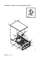
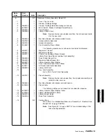
Страница 606: ...Assembly 6 Rackmount Library Assembly Model C21 PARTS 18 IBM 3570 MI...
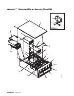
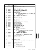
Страница 608: ...Assembly 7 Rackmount Library Assembly Model C22 PARTS 20 IBM 3570 MI...
Страница 611: ...Parts Catalog Parts Catalog PARTS 23...
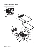
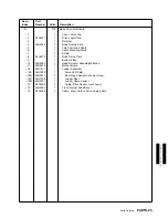
Страница 612: ...Assembly 8 Base Drive All Models PARTS 24 IBM 3570 MI...
Страница 614: ...PARTS 26 IBM 3570 MI...
Страница 629: ...wrap tool SCSI port PROC 77 INDEX Index Index 7...


