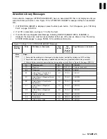


MAPS
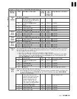
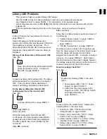
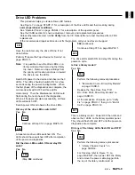
Drive LED Problems
This procedure helps you isolate Drive LED failures.
See Figure 7 on page START-11 for a description of the Drive LEDs and their meaning during
normal operational conditions.
See “Operator Panel” on page PANEL-1 for a description of the operator panel.
See the CARR section for check, adjustment, removal, and replacement procedures.
Unless otherwise directed, run Fix Verify from the CE Options Menu to test the drive after a FRU
replacement.
If the recommended repair actions do not fix the problem, call your next level of support.
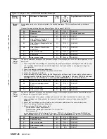
001
Have the customer vary the drive off-line, if not
done before.
Perform “Prepare the Tape Device for Service” on
page PROC-5.
Note: It is possible to see the drive LEDs on a
library model without removing the library
top cover. Remove a tape cartridge from
the priority cell location and look in toward
the drive to see the LEDs.
Switch ON power to the device and observe the 3
LEDs. The LEDs should all switch ON for a few
seconds during the power-on diagnostics. When
the first phase of the diagnostics are complete, the
microcode will switch OFF all three LEDs
momentarily. Then the Maintenance LED should
flash during the next phase of the diagnostics.
When all the tests complete successfully, all three
LEDs will switch OFF.
Switch power ON and observe the drive LEDs.
Did any of the drive LEDs switch ON?
Yes No
002
Continue at Step 012 on page MAPS-10.
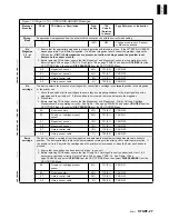
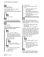
003
At least some drive LEDs switched ON. The
LEDs should have switched OFF after completion
of the power-on diagnostics.
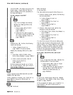
Did the drive LEDs switch ON and stay ON
solid?
Yes No
004
(Step 004 continues)
004 (continued)
Continue at Step 015 on page MAPS-11.
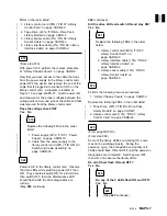
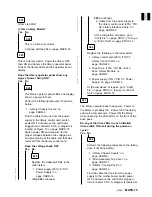
005
The drive LEDs switch ON and stay ON during the
power-on cycle.
Is this a library model?
Yes No
006
Perform the following removal procedures:
1. “Decorative Cover—Drive-Only Models”
on page CARR-5.
Replace the Tape Drive. See “FID
B3—Drive Pack, Drive-Only Models” on
page CARR-10.
At the completion of repairs, go to “Verify
Fix” on page PROC-7, then go to “End of
Call” on page PROC-12.
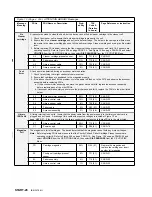
007
This is a library model. Power OFF then ON, and
observe the 3 LEDs on the library operator panel.
They should flash ON and OFF until the power-on
diagnostics are complete.
Did any of the library LEDs flash ON and OFF?
Yes No
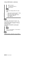
008
Perform the following remove procedures:
1. “Library Chassis Covers” on
page CARR-3.
For this step, refer to Figure 13 on
page MAPS-27, then power OFF the library
and remove the power cable plugged into
the top of the library control card at
MAPs
MAPS-9
Содержание Magstar MP 3570 C Series
Страница 1: ...IBM Magstar MP 3570 Tape Subsystem Maintenance Information C Series Models...
Страница 2: ......
Страница 12: ...x IBM 3570 MI...
Страница 46: ...MAPS 2 IBM 3570 MI...
Страница 56: ...Notes MAPS 12 IBM 3570 MI...
Страница 62: ...MAPS 18 IBM 3570 MI...
Страница 70: ...Notes MAPS 26 IBM 3570 MI...
Страница 72: ...MAPS 28 IBM 3570 MI...
Страница 84: ...Figure 22 Label Locations for Models Without Libraries INTRO 12 IBM 3570 MI...
Страница 87: ...Figure 25 Model C00 Drive INTRO Introduction INTRO 15...
Страница 95: ...Figure 29 Model C02 Stand Alone Library Model INTRO Introduction INTRO 23...
Страница 96: ...A 2 1 M 0 0 3 5 Figure 30 Model C11 Rack Mounted Library Model INTRO 24 IBM 3570 MI...
Страница 97: ...Figure 31 Model C12 Rack Mounted Library Model INTRO Introduction INTRO 25...
Страница 98: ...Figure 32 Model C21 Rack Mounted Library Model INTRO 26 IBM 3570 MI...
Страница 99: ...Figure 33 Model C22 Rack Mounted Library Model INTRO Introduction INTRO 27...
Страница 120: ...INTRO 48 IBM 3570 MI...
Страница 124: ...Figure 51 3570 Cartridge Magazine Figure 52 3570 Cartridge Magazine Lock Lever LIBRARY 4 IBM 3570 MI...
Страница 136: ...Figure 57 Model C02 Stand Alone Library Model LIBRARY 16 IBM 3570 MI...
Страница 137: ...A 2 1 M 0 0 3 5 Figure 58 Model C11 Rack Mounted Library Model LIBRARY Library LIBRARY 17...
Страница 138: ...Figure 59 Model C12 Rack Mounted Library Model LIBRARY 18 IBM 3570 MI...
Страница 139: ...Figure 60 Model C21 Rack Mounted Library Model LIBRARY Library LIBRARY 19...
Страница 144: ...LIBRARY 24 IBM 3570 MI...
Страница 192: ...Figure 108 Operator Menus PANEL 12 IBM 3570 MI...
Страница 206: ...Figure 128 Part 1 of 3 CE Panel Menu PANEL 26 IBM 3570 MI...
Страница 207: ...Figure 128 Part 2 of 3 CE Panel Menu PANEL Operator Panel PANEL 27...
Страница 208: ...Figure 128 Part 3 of 3 CE Panel Menu PANEL 28 IBM 3570 MI...
Страница 242: ...PANEL 62 IBM 3570 MI...
Страница 249: ...Korean Inspection INSP 7...
Страница 250: ...Korean INSP 8 IBM 3570 MI...
Страница 256: ...Figure 187 Support Slide left side Models C21 and C22 INSP 14 IBM 3570 MI...
Страница 260: ...INSP 18 IBM 3570 MI...
Страница 270: ...Figure 196 Model C00 Drive Inner Cover Configuration INST 10 IBM 3570 MI...
Страница 273: ...Figure 200 Drive Only Model C00 SCSI Connection INST Installation INST 13...
Страница 275: ...Figure 202 EIA Rack Template for Models C11 and C12 INST Installation INST 15...
Страница 276: ...This Page Left Intentionally Blank INST 16 IBM 3570 MI...
Страница 288: ...INST 28 IBM 3570 MI...
Страница 289: ...Figure 212 EIA Rack Template for Models C21 and C22 INST Installation INST 29...
Страница 290: ...This Page Left Intentionally Blank INST 30 IBM 3570 MI...
Страница 297: ...Figure 216 Attaching Cable Arm and Strain Relief Bracket INST Installation INST 37...
Страница 312: ...Figure 227 Rear View of Model C02 C12 or C22 INST 52 IBM 3570 MI...
Страница 319: ...Figure 237 Cable Routing Model C11 INST Installation INST 59...
Страница 320: ...Figure 238 Cable Routing Model C12 Figure 239 Cable length adjusting Models C11 and C12 INST 60 IBM 3570 MI...
Страница 321: ...Figure 240 Cable Routing Model C21 INST Installation INST 61...
Страница 322: ...Figure 241 Cable Routing Model C22 Figure 242 Cable length adjusting Models C21 and C22 INST 62 IBM 3570 MI...
Страница 328: ...INST 68 IBM 3570 MI...
Страница 345: ...Figure 251 Loading a Cartridge in a Magazine with Operator Side Facing Down PROC Common Procedures PROC 17...
Страница 348: ...Figure 252 Removing a Stuck Cartridge From a Drive PROC 20 IBM 3570 MI...
Страница 349: ...Figure 253 Drive Front View Unloaded Figure 254 Drive Front View Loaded PROC Common Procedures PROC 21...
Страница 369: ...Figure 260 Blank Error Log Analysis Work Sheet PROC Common Procedures PROC 41...
Страница 371: ...Figure 263 Example Error Log Analysis Work Sheet PROC Common Procedures PROC 43...
Страница 396: ...6 When the Tape Device Test menu is displayed select Exit test menu 3 PROC 68 IBM 3570 MI...
Страница 420: ...PROC 92 IBM 3570 MI...
Страница 424: ...Figure 270 Library Model C01 Exploded View CARR 4 IBM 3570 MI...
Страница 435: ...Figure 274 Base Drive FRU Breakout CARR Checks Adjustments Removals and Replacements CARR 15...
Страница 448: ...Figure 279 Library Front Door Assembly Holding Screws CARR 28 IBM 3570 MI...
Страница 456: ...CARR 36 IBM 3570 MI...
Страница 504: ...APPENDC 2 IBM 3570 MI...
Страница 521: ...APPENDC Appendix C APPENDC 19...
Страница 522: ...Notes APPENDC 20 IBM 3570 MI...
Страница 532: ...APPENDC 30 IBM 3570 MI...
Страница 537: ...Figure 312 Library Model C01 Exploded View APPENDD Appendix D APPENDD 5...
Страница 541: ...Figure 315 Basic Drive All Models APPENDD Appendix D APPENDD 9...
Страница 546: ...Figure 317 Base Drive FRU Breakout APPENDD 14 IBM 3570 MI...
Страница 551: ...Figure 318 Base Drive Head Actuator Assembly Close up APPENDD Appendix D APPENDD 19...
Страница 556: ...Head Actuator Cable Holding Tool Template This page left intentionally blank APPENDD 24 IBM 3570 MI...
Страница 557: ...APPENDD Appendix D APPENDD 25...
Страница 563: ...Figure 326 Drive Loader Assembly Exploded View APPENDD Appendix D APPENDD 31...
Страница 580: ...Figure 332 Library Front Door Assembly Holding Screws APPENDD 48 IBM 3570 MI...
Страница 591: ...Parts Catalog Parts Catalog PARTS 3...
Страница 592: ...Assembly 1 Rackmount Library Assembly Model C11 PARTS 4 IBM 3570 MI...
Страница 594: ...Assembly 2 Desktop Drive Model C00 PARTS 6 IBM 3570 MI...
Страница 596: ...Assembly 3 Desktop Library Assembly Model C01 PARTS 8 IBM 3570 MI...
Страница 598: ...Assembly 4 Rackmount Library Assembly Model C12 PARTS 10 IBM 3570 MI...
Страница 601: ...Parts Catalog Parts Catalog PARTS 13...
Страница 602: ...Assembly 5 Desktop Library Assembly Model C02 PARTS 14 IBM 3570 MI...
Страница 605: ...Parts Catalog Parts Catalog PARTS 17...
Страница 606: ...Assembly 6 Rackmount Library Assembly Model C21 PARTS 18 IBM 3570 MI...
Страница 608: ...Assembly 7 Rackmount Library Assembly Model C22 PARTS 20 IBM 3570 MI...
Страница 611: ...Parts Catalog Parts Catalog PARTS 23...
Страница 612: ...Assembly 8 Base Drive All Models PARTS 24 IBM 3570 MI...
Страница 614: ...PARTS 26 IBM 3570 MI...
Страница 629: ...wrap tool SCSI port PROC 77 INDEX Index Index 7...


