


Hardware Reset
In library models, a hardware reset equivalent to a power-on reset of the drive unit and library can be
done from the operator panel by pressing the Change Mode push-button, the Scroll Up push-button and
the Enter push-button at the same time (Change-Mode+Scroll-Up+Enter).
In drive-only models, switch power OFF and then back ON to create a hardware reset.
End of Call
Note: When you switch power OFF to the drive or library device, wait approximately 5 seconds before
switching power ON again.
1. Set the Power switch to the ON position.
The power-on test takes approximately 2.5 minutes to complete, and is automatically performed when
the 3570 power is switched on. The tests that run depend on the model of 3570 you have installed:
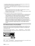
Model C00 Drive
a. The drive LEDs will light solid for a time, then go out.
b. The Maintenance LED will blink while the diagnostic is running.
c. When the test is concluded without error, the drive LEDs will all go off.
d. If an error occurs, the drive LEDs will flash quickly, then begin to send the FID via flashing
LEDs. To decode these flashing LEDs, see Figure 245 on page PROC-8.
For library Models:
a. The three LEDs will go on solid momentarily, then will begin to blink as the bring up
diagnostics run.
b. The picker assembly will move back and forth from side to side, then will begin to calibrate its
position in relation to the magazines.
c. The picker assembly will then sense each cartridge and indicate full or empty slots in the
magazine.
d. If an error occurs, it is displayed in the library operator panel display.
If a failure occurs on any model, go to the START section for further analysis.
|
2. If you replaced the drive, do the following:
a. Ensure the microcode was updated.
b. Ensure the drive options and customer options are correct. See “Set Drive Options—Library
Models” on page INST-42.
3. Run tests for the areas you have been making repairs to; if the drive was repaired, run the Drive Test,
if the library was being repaired, run the library Test:
a. For the procedure to verify the fix on library models, continue at “CE Verify Fix on Library Models”
on page PROC-10 then return here.
b. For the procedure to verify the fix on drive-only models, continue at “Verify Fix—Drive-Only
Models” on page PROC-7 then return here.
4. If this is a drive-only model, continue at step 11 on page PROC-13.
5. If your machine is a library model, continue at step 6 on page PROC-13.
Library Models Only
PROC-12
IBM 3570 MI
Содержание Magstar MP 3570 C Series
Страница 1: ...IBM Magstar MP 3570 Tape Subsystem Maintenance Information C Series Models...
Страница 2: ......
Страница 12: ...x IBM 3570 MI...
Страница 46: ...MAPS 2 IBM 3570 MI...
Страница 56: ...Notes MAPS 12 IBM 3570 MI...
Страница 62: ...MAPS 18 IBM 3570 MI...
Страница 70: ...Notes MAPS 26 IBM 3570 MI...
Страница 72: ...MAPS 28 IBM 3570 MI...
Страница 84: ...Figure 22 Label Locations for Models Without Libraries INTRO 12 IBM 3570 MI...
Страница 87: ...Figure 25 Model C00 Drive INTRO Introduction INTRO 15...
Страница 95: ...Figure 29 Model C02 Stand Alone Library Model INTRO Introduction INTRO 23...
Страница 96: ...A 2 1 M 0 0 3 5 Figure 30 Model C11 Rack Mounted Library Model INTRO 24 IBM 3570 MI...
Страница 97: ...Figure 31 Model C12 Rack Mounted Library Model INTRO Introduction INTRO 25...
Страница 98: ...Figure 32 Model C21 Rack Mounted Library Model INTRO 26 IBM 3570 MI...
Страница 99: ...Figure 33 Model C22 Rack Mounted Library Model INTRO Introduction INTRO 27...
Страница 120: ...INTRO 48 IBM 3570 MI...
Страница 124: ...Figure 51 3570 Cartridge Magazine Figure 52 3570 Cartridge Magazine Lock Lever LIBRARY 4 IBM 3570 MI...
Страница 136: ...Figure 57 Model C02 Stand Alone Library Model LIBRARY 16 IBM 3570 MI...
Страница 137: ...A 2 1 M 0 0 3 5 Figure 58 Model C11 Rack Mounted Library Model LIBRARY Library LIBRARY 17...
Страница 138: ...Figure 59 Model C12 Rack Mounted Library Model LIBRARY 18 IBM 3570 MI...
Страница 139: ...Figure 60 Model C21 Rack Mounted Library Model LIBRARY Library LIBRARY 19...
Страница 144: ...LIBRARY 24 IBM 3570 MI...
Страница 192: ...Figure 108 Operator Menus PANEL 12 IBM 3570 MI...
Страница 206: ...Figure 128 Part 1 of 3 CE Panel Menu PANEL 26 IBM 3570 MI...
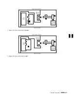
Страница 207: ...Figure 128 Part 2 of 3 CE Panel Menu PANEL Operator Panel PANEL 27...
Страница 208: ...Figure 128 Part 3 of 3 CE Panel Menu PANEL 28 IBM 3570 MI...
Страница 242: ...PANEL 62 IBM 3570 MI...
Страница 249: ...Korean Inspection INSP 7...
Страница 250: ...Korean INSP 8 IBM 3570 MI...
Страница 256: ...Figure 187 Support Slide left side Models C21 and C22 INSP 14 IBM 3570 MI...
Страница 260: ...INSP 18 IBM 3570 MI...
Страница 270: ...Figure 196 Model C00 Drive Inner Cover Configuration INST 10 IBM 3570 MI...
Страница 273: ...Figure 200 Drive Only Model C00 SCSI Connection INST Installation INST 13...
Страница 275: ...Figure 202 EIA Rack Template for Models C11 and C12 INST Installation INST 15...
Страница 276: ...This Page Left Intentionally Blank INST 16 IBM 3570 MI...
Страница 288: ...INST 28 IBM 3570 MI...
Страница 289: ...Figure 212 EIA Rack Template for Models C21 and C22 INST Installation INST 29...
Страница 290: ...This Page Left Intentionally Blank INST 30 IBM 3570 MI...
Страница 297: ...Figure 216 Attaching Cable Arm and Strain Relief Bracket INST Installation INST 37...
Страница 312: ...Figure 227 Rear View of Model C02 C12 or C22 INST 52 IBM 3570 MI...
Страница 319: ...Figure 237 Cable Routing Model C11 INST Installation INST 59...
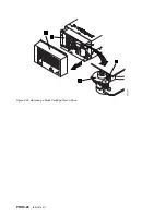
Страница 320: ...Figure 238 Cable Routing Model C12 Figure 239 Cable length adjusting Models C11 and C12 INST 60 IBM 3570 MI...
Страница 321: ...Figure 240 Cable Routing Model C21 INST Installation INST 61...
Страница 322: ...Figure 241 Cable Routing Model C22 Figure 242 Cable length adjusting Models C21 and C22 INST 62 IBM 3570 MI...
Страница 328: ...INST 68 IBM 3570 MI...
Страница 345: ...Figure 251 Loading a Cartridge in a Magazine with Operator Side Facing Down PROC Common Procedures PROC 17...
Страница 348: ...Figure 252 Removing a Stuck Cartridge From a Drive PROC 20 IBM 3570 MI...
Страница 349: ...Figure 253 Drive Front View Unloaded Figure 254 Drive Front View Loaded PROC Common Procedures PROC 21...
Страница 369: ...Figure 260 Blank Error Log Analysis Work Sheet PROC Common Procedures PROC 41...
Страница 371: ...Figure 263 Example Error Log Analysis Work Sheet PROC Common Procedures PROC 43...
Страница 396: ...6 When the Tape Device Test menu is displayed select Exit test menu 3 PROC 68 IBM 3570 MI...
Страница 420: ...PROC 92 IBM 3570 MI...
Страница 424: ...Figure 270 Library Model C01 Exploded View CARR 4 IBM 3570 MI...
Страница 435: ...Figure 274 Base Drive FRU Breakout CARR Checks Adjustments Removals and Replacements CARR 15...
Страница 448: ...Figure 279 Library Front Door Assembly Holding Screws CARR 28 IBM 3570 MI...
Страница 456: ...CARR 36 IBM 3570 MI...
Страница 504: ...APPENDC 2 IBM 3570 MI...
Страница 521: ...APPENDC Appendix C APPENDC 19...
Страница 522: ...Notes APPENDC 20 IBM 3570 MI...
Страница 532: ...APPENDC 30 IBM 3570 MI...
Страница 537: ...Figure 312 Library Model C01 Exploded View APPENDD Appendix D APPENDD 5...
Страница 541: ...Figure 315 Basic Drive All Models APPENDD Appendix D APPENDD 9...
Страница 546: ...Figure 317 Base Drive FRU Breakout APPENDD 14 IBM 3570 MI...
Страница 551: ...Figure 318 Base Drive Head Actuator Assembly Close up APPENDD Appendix D APPENDD 19...
Страница 556: ...Head Actuator Cable Holding Tool Template This page left intentionally blank APPENDD 24 IBM 3570 MI...
Страница 557: ...APPENDD Appendix D APPENDD 25...
Страница 563: ...Figure 326 Drive Loader Assembly Exploded View APPENDD Appendix D APPENDD 31...
Страница 580: ...Figure 332 Library Front Door Assembly Holding Screws APPENDD 48 IBM 3570 MI...
Страница 591: ...Parts Catalog Parts Catalog PARTS 3...
Страница 592: ...Assembly 1 Rackmount Library Assembly Model C11 PARTS 4 IBM 3570 MI...
Страница 594: ...Assembly 2 Desktop Drive Model C00 PARTS 6 IBM 3570 MI...
Страница 596: ...Assembly 3 Desktop Library Assembly Model C01 PARTS 8 IBM 3570 MI...
Страница 598: ...Assembly 4 Rackmount Library Assembly Model C12 PARTS 10 IBM 3570 MI...
Страница 601: ...Parts Catalog Parts Catalog PARTS 13...
Страница 602: ...Assembly 5 Desktop Library Assembly Model C02 PARTS 14 IBM 3570 MI...
Страница 605: ...Parts Catalog Parts Catalog PARTS 17...
Страница 606: ...Assembly 6 Rackmount Library Assembly Model C21 PARTS 18 IBM 3570 MI...
Страница 608: ...Assembly 7 Rackmount Library Assembly Model C22 PARTS 20 IBM 3570 MI...
Страница 611: ...Parts Catalog Parts Catalog PARTS 23...
Страница 612: ...Assembly 8 Base Drive All Models PARTS 24 IBM 3570 MI...
Страница 614: ...PARTS 26 IBM 3570 MI...
Страница 629: ...wrap tool SCSI port PROC 77 INDEX Index Index 7...


