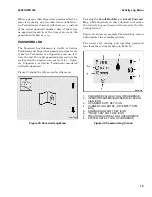
If the battery charge drops below 25%, the "low bat-
tery alarm" sounds and the BDI begins flashing.
The "low battery alarm" also sounds if the lift truck
is turned ON when the BSOC is below 25%. If the
BSOC drops to 20%, the leftmost segment changes
to an outline and a second "low battery alarm"
sounds. The lift truck will be subjected to operating
and performance limitations if the BSOC drops be-
low 20%.
DIRECTION AND PARKING BRAKE
INDICATORS
These indicators are displayed in the center of the
Operating Screen, as shown in Figure 11.
• An up-arrow indicates the truck will move
forward if the accelerator is pressed.
• A down-arrow indicates the truck will move
backward (reverse) if the accelerator is
pressed.
• A solid "N" indicates the truck will not move
if the accelerator is pressed, though it can
still roll if the service brake is released.
• The parking brake icon is a "P" with a circle
around it to represent a wheel and arcs
around the circle that represent brakes.
When this icon is displayed, it indicates the
truck parking brake is applied and the truck
will not move if the accelerator is pressed.
HAZARD FLASHERS AND LIGHTING
CONTROLS
If the lift truck is equipped with CAN controlled
hazard flashers and lighting controls, the icons that
indicate the status of the lift truck's hazard flash-
ers and lights are displayed on the Operating
Screen. The soft keys the operator can use to con-
trol these lights are located near the Operating
Screen.
• The Front Work Light Icon, on the lower
right of the screen, is always visible. The op-
erator can turn the front lights ON and OFF
by pressing the 2 soft key.
• The Rear Work Light Icon, on the upper
right of the screen, is always visible. The op-
erator can turn the rear lights ON and OFF
by pressing the 3 soft key.
• The Hazard Flashers Icon, a triangle on the
lower left of the screen, is always visible if
the lift truck is equipped with hazard flash-
ers. The operator can press the # soft key to
toggle the truck's hazard flashers ON and
OFF.
STEER ANGLE INDICATOR
The Steer Angle indicator is displayed in the lower
center of the Operating Screen, as shown in Fig-
ure 11. The purpose of this indicator is to show the
operator the current steer angle (the direction of
the tires that steer the truck). This informs the op-
erator which way the truck will move if the acceler-
ator pedal is pressed, given the current steer angle.
The Steer Angle indicator shows the steering angle
to the nearest 22.5° from full left, to full right.
SYSTEM TIME
The System Time for the lift truck, shown as 12:34
in Figure 11, appears in the lower right corner of
the Operating Screen. System time can be reset by
a Supervisor or Service Technician using the proce-
dures described in Display Menu. If the Clock Hour
Format is set to a 12-hour clock, the time numbers
will be followed by an "A" (AM) or a "P" (PM) as ap-
propriate. Otherwise, the system time uses a 24-
hour clock.
LOAD WEIGHT INDICATOR
The Load Weight indicator for the lift truck, shown
as 99999 beside the Load Weight Icon in Figure 11,
appears at the midpoint of the right side of the Op-
erating Screen. If the lift truck supports the Load
Weight feature, the Operating Screen will display
the load weight during any mast hydraulic com-
mand and for five seconds afterwards.
The Load Weight Icon indicates whether lb (pound)
or kg (kilogram) units are being used. Use the pro-
cedures described in the Set Units Menu topic in
the Display Menu section to set the load units for
this lift truck. Use the procedures in the Load
Weight Display topic in the Calibration Menu sec-
tion to calibrate the load weight for this lift truck.
2200 SRM 1336
System Off/Alert Screens
63
Содержание A1.3-1.5XNT
Страница 6: ... THE QUALITY KEEPERS HYSTER APPROVED PARTS ...
Страница 9: ...Figure 3 Technician Flowchart Sheet 1 of 4 2200 SRM 1336 Menu Flowchart 3 ...
Страница 10: ...Figure 3 Technician Flowchart Sheet 2 of 4 Menu Flowchart 2200 SRM 1336 4 ...
Страница 11: ...Figure 3 Technician Flowchart Sheet 3 of 4 2200 SRM 1336 Menu Flowchart 5 ...
Страница 12: ...Figure 3 Technician Flowchart Sheet 4 of 4 Menu Flowchart 2200 SRM 1336 6 ...
Страница 123: ......
Страница 124: ...TECHNICAL PUBLICATIONS 2200 SRM 1336 2 14 8 13 4 13 12 12 3 12 12 11 ...


