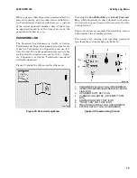
Figure 9. Operating Screen
NOTE:
Icons for the front and rear work lights are
shown. These are optional features.
The icons, indicators, and numbers on the Operat-
ing Screen are explained in the topics that follow.
PERFORMANCE MODE CONTROLS
The Performance Mode controls are shown in Fig-
ure 10.
The current performance mode is shown on the Op-
erating Screen. There are four available perform-
ance modes, numbered 1, 2, 3, and 4. Performance
mode 4 provides the maximum performance. If
passwords are enabled, the last active performance
mode on the truck is displayed on the screen when
the truck is powered On, unless the current opera-
tor has been assigned a lower available perform-
ance mode. The maximum performance mode al-
lowed for each operator is set by the Supervisor or
Service Technician during the Add/Remove Pass-
word section of Truck Setup. See the Password
Screen topic for more information. Depending on
the maximum performance mode allowed, it may be
possible for the operator to use the Performance
Mode soft keys on the Display Panel to change the
current performance mode.
• MODE 4 - This is the highest performance
mode. Other modes are a lower percentage of
Mode 4.
• MODE 3 - Top speed is the same as Mode 4.
Acceleration is 80 percent of Mode 4.
• MODE 2 - Top speed is 80 percent of Mode 4.
Acceleration is 70 percent of Mode 4.
• MODE 1 - Top speed is 60 percent of Mode 4.
Acceleration is 60 percent of Mode 4.
Pressing the "Hare" soft key, 4, increases the cur-
rent mode and pressing the "Tortoise" soft key, 1,
decreases the current mode, assuming performance
mode change is available to the current operator.
The performance mode can be changed only when
both the hydraulic and direction controls are in
Neutral and the truck is stopped. If a performance
mode change is attempted at a time when either of
these conditions is not met, the newly selected
mode will flash and the change will not occur until
the necessary conditions are met.
Operating Screen
2200 SRM 1336
60
Содержание A1.3-1.5XNT
Страница 6: ... THE QUALITY KEEPERS HYSTER APPROVED PARTS ...
Страница 9: ...Figure 3 Technician Flowchart Sheet 1 of 4 2200 SRM 1336 Menu Flowchart 3 ...
Страница 10: ...Figure 3 Technician Flowchart Sheet 2 of 4 Menu Flowchart 2200 SRM 1336 4 ...
Страница 11: ...Figure 3 Technician Flowchart Sheet 3 of 4 2200 SRM 1336 Menu Flowchart 5 ...
Страница 12: ...Figure 3 Technician Flowchart Sheet 4 of 4 Menu Flowchart 2200 SRM 1336 6 ...
Страница 123: ......
Страница 124: ...TECHNICAL PUBLICATIONS 2200 SRM 1336 2 14 8 13 4 13 12 12 3 12 12 11 ...


