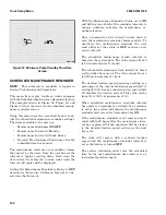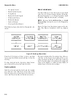
Figure 62. RTST Setup Screen
The icon at the top left of the screen is for the delay
time. When a box is around the current value, press
the Enter Key. Then use the 2 or 3 soft key to step
through the available values for the delay time, 0,
0.1, 0.2, 0.4, 0.6, 0.8, 1.0, 2.0, 3.0 seconds or Contin-
uous and press the Enter Key to save the new
value. When the delay time is set to 0, this feature
is deactivated. When set to Continuous, the delay
time is infinite (limitless).
The lift truck icon in Figure 62 indicates the mast
assembly is programmed to return to the set tilt
angle only when it is moving forward, which is the
Forward option. To set up the mast assembly so
that it returns to the set tilt whether it is moving
forward or backward, use the 2 or 3 soft key to set
the RTSH direction to Both.
AUTO POWER-OFF TIME DELAY
NOTE:
This submenu is available to logged in
Service Technicians and Supervisors.
This menu can be used to shut the lift truck OFF if
the operator has left the seat for a set number of
minutes.
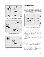
This menu can be used to adjust the setting for the
amount of time before the truck enters the Power
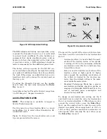
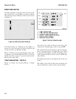
Off mode. Figure 63 shows an Auto Power-Off De-
lay Setup Screen that has a 20m delay setting
value, which is a 20 minute delay.
Figure 63. Auto Power-Off Time Delay Setup
Screen
To change the Auto Power-Off Time Delay setting,
select the current value. When a box is around it,
press the Enter Key, then use the number keys to
enter a value from 0 to 30 minutes and press the
Enter Key to save the new setting.
IMPACT MONITOR SETTINGS
NOTE:
This submenu is available to logged in
Service Technicians and Supervisors. It is visible
only on trucks equipped with the Impact Monitor-
ing feature.
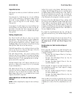
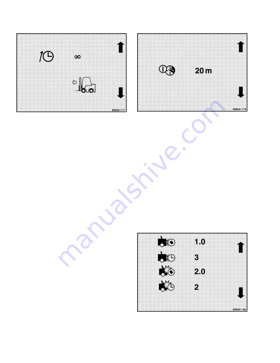
This menu provides a way to adjust the settings the
impact monitor uses when it detects impacts. Fig-
ure 64 shows the Impact Monitor Settings Screen.
Figure 64. Impact Monitor Settings Screen
Truck Setup Menu
2200 SRM 1336
104
Содержание A1.3-1.5XNT
Страница 6: ... THE QUALITY KEEPERS HYSTER APPROVED PARTS ...
Страница 9: ...Figure 3 Technician Flowchart Sheet 1 of 4 2200 SRM 1336 Menu Flowchart 3 ...
Страница 10: ...Figure 3 Technician Flowchart Sheet 2 of 4 Menu Flowchart 2200 SRM 1336 4 ...
Страница 11: ...Figure 3 Technician Flowchart Sheet 3 of 4 2200 SRM 1336 Menu Flowchart 5 ...
Страница 12: ...Figure 3 Technician Flowchart Sheet 4 of 4 Menu Flowchart 2200 SRM 1336 6 ...
Страница 123: ......
Страница 124: ...TECHNICAL PUBLICATIONS 2200 SRM 1336 2 14 8 13 4 13 12 12 3 12 12 11 ...

