E-HYDRAULIC VALVES
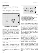
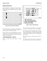
This screen is a submenu that displays the electri-
cal current output information from the hydraulic
controls known as Hydraulic Functions 1-4. It pro-
vides current feedback from each of the equipped E-
Hydraulic valves (also called Electro-Hydraulic
valves). Data shown includes amperes (A) and the
present state of the Auxiliary Function Solenoid;
that is, whether it is Engaged or Not Engaged. This
menu displays only on trucks equipped with E-Hy-
draulics, which provides hydraulic functions 1-4.
See Figure 79.
1. HYDRAULIC FUNCTION 1
2. AUXILIARY FUNCTION SOLENOID
Figure 80. E-Hydraulic Valves Menu
The value on the right hand side of the Hydraulic
Function 1 Icon at the top of the screen shows the
Hydraulic Function 1 amperes of the valve assem-
bly for lift/lower.
The second value down from the top of the screen
shows the Hydraulic Function 2 amperes for the
valve assembly for tilt forward/back.
The third, fourth, and fifth values down are for the
Auxiliary 1 and 2 inputs. Since these inputs are op-
tional, they are displayed only if the truck is equip-
ped with them. The third value down shows the
Hydraulic Function 3 (Auxiliary 1 input) amperes
and the fourth value down shows the Hydraulic
Function 4 (Auxiliary 2 input) amperes.
When the ampere value is a positive number, it is a
value in the A direction (the A direction means mo-
tion toward the front or the right of the truck). If
the value is a negative number, the value shown is
in the B direction (motion toward the rear or the
left of the truck).
If the forklift truck is equipped with this function,
the state of the auxiliary function solenoid is dis-
played. This icon at the top of the screen indicates
whether the valve assembly is released or pressed.
If the auxiliary function solenoid is being driven,
the engaged icon is displayed and the icon has an
up arrow. If this solenoid is not being driven, the
disengaged icon is shown and the icon has a down
arrow.
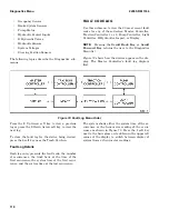
The Forklift Truck Icon in the top right corner of
the screen shows whether truck operations are ena-
bled or disabled. If a Null Icon overlays the Forklift
Truck Icon, traction and hydraulics are deactiva-
ted. To enable traction and hydraulics, press the 2
soft key.
HYDRAULIC SENSORS
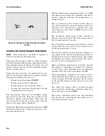
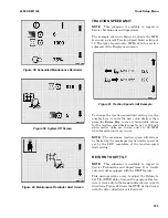
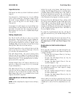
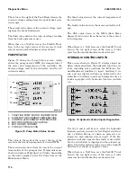
Figure 81 displays the current temperature of the
hydraulic tank and the current voltages of the mast
tilt sensor, the mast height sensor, and the hy-
draulic pressure sensor that detects load weight.
Figure 81. Mast Diagnostics Screen
The current temperature of the hydraulic tank is
the value at the top of the screen.
The second value down from the top of the screen is
the current voltage of the mast tilt sensor.
The third value down is the current voltage of the
mast height sensor.
2200 SRM 1336
Diagnostics Menu
115
Содержание A1.3-1.5XNT
Страница 6: ... THE QUALITY KEEPERS HYSTER APPROVED PARTS ...
Страница 9: ...Figure 3 Technician Flowchart Sheet 1 of 4 2200 SRM 1336 Menu Flowchart 3 ...
Страница 10: ...Figure 3 Technician Flowchart Sheet 2 of 4 Menu Flowchart 2200 SRM 1336 4 ...
Страница 11: ...Figure 3 Technician Flowchart Sheet 3 of 4 2200 SRM 1336 Menu Flowchart 5 ...
Страница 12: ...Figure 3 Technician Flowchart Sheet 4 of 4 Menu Flowchart 2200 SRM 1336 6 ...
Страница 123: ......
Страница 124: ...TECHNICAL PUBLICATIONS 2200 SRM 1336 2 14 8 13 4 13 12 12 3 12 12 11 ...


