


The soft keys include the 1 and 4 keys on the left,
the 2 and 3 keys on the right, and the # and * keys
below the Operating Screen. There are no icon indi-
cators for the soft keys.
The * soft key serves as an Enter Key in all menus
except when using the Operator Checklist (see the
Operator Checklist topic in the Truck Setup Menu
section). In a lot of menus, the 2 and 3 soft keys are
programmed for navigating up or down in the menu
to the setting value you want to change. Also, in
most but not all menus, the 2 and 3 soft keys are
programmed for moving up or down though the
available values or options for the currently selec-
ted setting. When this is the case, the up and down
arrows are displayed on the right side of the screen.
The following example shows how to use the soft
keys.
How to Change the Battery Voltage Setting
1.
Starting from the main menu, use the Scroll
Back Key (
◂
—) or Scroll Forward Key (—
▸
) to navigate to the Truck Setup Title
Screen and press the Enter Key (*).
2.
Use the 2 or 3 arrow soft keys to step
through the menus to the Battery Setup sub-
menu (the title screen of this submenu has a
battery icon on it) and press the Enter Key.
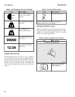
3.
Press the 2 or 3 arrow soft key to "move to"
the value located to the right of the top icon
and the system will place a "selection box"
around the value. This number indicates the
current battery voltage, such as 36.
4.
With the selection box around the battery
voltage value, press the Enter Key.
5.
Use the 2 and 3 arrow soft keys to move up
or down though the available values (36, 48,
72, and 80) until 48 is displayed, then press
the Enter Key.
The system stores the 48 Volt value and be-
gins using it as the new battery voltage set-
ting.
NOTE:
While changing a setting, all other sub-
items (setting items) disappear.
Entering Numbers
The preceding example shows how the system al-
lows a user to select one value out of a series of val-
ues. In some menus, you will use the number keys
(0 through 9) to enter a value directly. These are:
• The 1, 2, 3, and 4 soft keys. These keys can
be used as number keys only in the menus
that accept numerical input. These keys are
programmed for use as soft keys in most me-
nus.
• The 5, 6, 7, 8, 9, and 0 keys. These keys can
be used to enter numbers in menus that al-
low numerical input. These keys are not soft
keys in any menu.
Passwords are a special case of entering numbers.
The user is required to enter a five digit “password”
number, such as 15324, on the Password Screen.
This number must consist only of the numbers 1, 2,
3, 4, 5, 6, 7, 8, and 9 and is entered using the 1, 2,
3, 4, 5, 6, 7, 8, and 9 keys. Pressing any other nu-
meric key has no effect.
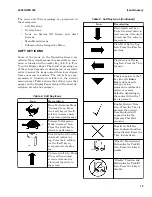
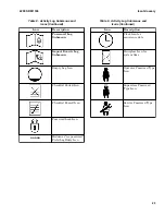
Icon Glossary
INTRODUCTION
An icon is a symbol that conveys a unique meaning
without words, such as an arrow. The Operating
Screen on this lift truck presents information to an
operator solely through the use of symbols which
are mostly icons, along with some numbers and a
few text characters. Icons make it possible to simul-
taneously display up to 12 kinds of information
graphically in a small space. In addition, the use of
icons reduces the difficulty of communicating with
operators who speak different languages.
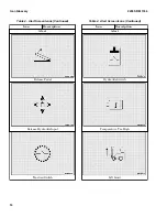
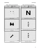
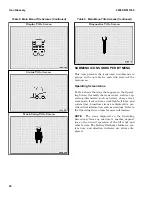
The meaning of some icons is apparent when the
icon appears by itself, such as the seat belt icon.
Other icons need to have numeric information dis-
played alongside them to present information, such
as when 24 appears beside the clock icon to indi-
cate the times are being displayed using the 24-
hour clock system. Sometimes two icons are dis-
played side by side to convey information, such as
when the icon that means "enabled" is shown be-
side the rear lights icon. Also, two icons can be dis-
played at the same time, one over the other, which
is discussed in the Overlay Icons topic.
Icon Glossary
2200 SRM 1336
12
Содержание A1.3-1.5XNT
Страница 6: ... THE QUALITY KEEPERS HYSTER APPROVED PARTS ...
Страница 9: ...Figure 3 Technician Flowchart Sheet 1 of 4 2200 SRM 1336 Menu Flowchart 3 ...
Страница 10: ...Figure 3 Technician Flowchart Sheet 2 of 4 Menu Flowchart 2200 SRM 1336 4 ...
Страница 11: ...Figure 3 Technician Flowchart Sheet 3 of 4 2200 SRM 1336 Menu Flowchart 5 ...
Страница 12: ...Figure 3 Technician Flowchart Sheet 4 of 4 Menu Flowchart 2200 SRM 1336 6 ...
Страница 123: ......
Страница 124: ...TECHNICAL PUBLICATIONS 2200 SRM 1336 2 14 8 13 4 13 12 12 3 12 12 11 ...


