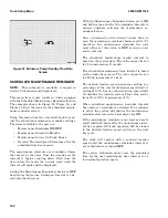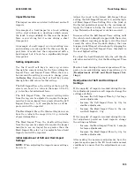
The value to the right of the Park Brake Icon is the
current voltage reading from the park brake's posi-
tion sensor.
The second value down is the current voltage read-
ing from the brake fluid sensor.
The third value down is the current voltage reading
from the brake pressure sensor.
When there is a Null Icon over the Forklift Truck
Icon in the top right corner of the screen, it indi-
cates traction and hydraulics are deactivated.
PUMP STATUS
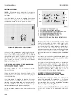
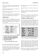
Figure 78 shows the Pump Status screen, which
shows the pump motor's RPM, the temperature of
the motor and temperature of the controller, the
battery voltage read by the controller, and the AC
current reading.
1. TRACTION PUMP MOTOR CURRENT RPM
2. PUMP MOTOR CURRENT TEMPERATURE
3. CONTROLLER CURRENT TEMPERATURE
4. MOTOR CONTROLLER VOLTAGE
5. MOTOR RMS CURRENT
6. FORK LIFT TRUCK ICON
Figure 78. Pump Motor Status Screen
The value to the right of the icon at the top of the
screen is the traction pump motor's current RPM.
The second value down from the top is the current
temperature of the pump motor. Temperatures are
shown in degrees Fahrenheit or Celsius, depending
on the units assigned in the Set Units item on the
Maintenance Menu.
The third value down is the current temperature of
the controller.
The fourth value down is the motor controller volt-
age.
The fifth value down is the RMS (Root Mean
Squared) AC current from the motor to the control-
ler in Amperes.
When there is a Null Icon over the Forklift Truck
Icon in the top right corner of the screen, it indi-
cates traction and hydraulics are deactivated.
HYDRAULIC CONTROL INPUTS
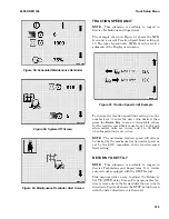
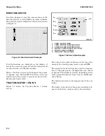
This screen, shown in Figure 79, displays input po-
sition information from the hydraulic function con-
trols, including lever positions for lift/lower, for-
ward/backward, Auxiliary 1 input, Auxiliary 2 in-
put, and any digital switches as indicated by the
controllers. Auxiliary inputs are displayed only on
trucks equipped with hydraulic function controls
3-4.
Figure 79. Hydraulic Control Inputs Diagnostics
Use the 1 and 4 soft keys to select the hydraulic
function control you want to view. Digital switch in-
put, or Button Status, is shown as pressed or re-
leased for each displayed lever input. If the Hy-
draulics controller reports the switch is not availa-
ble, the switch state is displayed in the released po-
sition. Controller motions to the rear of the truck (B
direction) are shown as negative values.
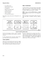
When there is a Null Icon over the Forklift Truck
Icon in the top right corner of the screen, it indi-
cates traction and hydraulics are deactivated.
Diagnostics Menu
2200 SRM 1336
114
Содержание A1.3-1.5XNT
Страница 6: ... THE QUALITY KEEPERS HYSTER APPROVED PARTS ...
Страница 9: ...Figure 3 Technician Flowchart Sheet 1 of 4 2200 SRM 1336 Menu Flowchart 3 ...
Страница 10: ...Figure 3 Technician Flowchart Sheet 2 of 4 Menu Flowchart 2200 SRM 1336 4 ...
Страница 11: ...Figure 3 Technician Flowchart Sheet 3 of 4 2200 SRM 1336 Menu Flowchart 5 ...
Страница 12: ...Figure 3 Technician Flowchart Sheet 4 of 4 Menu Flowchart 2200 SRM 1336 6 ...
Страница 123: ......
Страница 124: ...TECHNICAL PUBLICATIONS 2200 SRM 1336 2 14 8 13 4 13 12 12 3 12 12 11 ...


