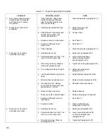
TABLE 7-1. 7035B TROUBLESHOOTING INDEX (Continued)
PROBLEM
POSSIBLE CAUSE
CURE
15.
Y-axis acceleration too
a.
Drive string too loose. Measure
a.
Tighten drive string
slow.
tension per paragraph 5-66.
(see paragraph 5-67).
b.
Input signal source impedance too high
b.
Lower source impedance and/or
(1 mv/inch, 0.4 mv/cm) range only.
increase amplifier gain (see
paragraph 5-92).
c.
Bearing in drive train faulty.
c.
Replace bearing.
d.
Faulty neon bulb in photochopper.
d.
Replace bulb (aging not required).
e.
Excessive differential noise on
e.
See Table 1-1.
input signal.
f.
Excessive friction.
f.
Clean and lubricate per
paragraphs 5-9 and 5-12.
16.
X-axis acceleration too
a.
Drive belt too loose. Measure
a.
Tighten drive belt
slow.
tension per paragraph 5-78.
(paragraph 5-79).
b.
Input signal source impedance too
b.
Lower source impedance
high (1 mv/inch, 0.4 mv/cm)
and/or increase amplifier
range only.
gain (see paragraph 5-92).
c.
Bearing in drive train faulty.
c.
Replace bearing (see
paragraph 5-87).
d.
Faulty neon bulb in photochopper.
d.
Replace bulb (aging not
required).
e.
Excessive differential noise on
e.
See Table 1-1.
input signal.
f.
Excessive friction.
f.
Clean and lubricate per
paragraphs 5-9 and 5-12.
17.
Maximum pen speed too
a.
Power line voltage too low. (Pen
a.
Increase line voltage (i.e.,
slow.
speed is dependent on line voltage.)
with Variac).
b.
Operating on 115-vol line with
b.
Correct switch position.
voltage selector switch in 230-
volt position (front panel neon
won't light).
c.
Bearing in drive train faulty.
c.
Replace bearing. (See
paragraph 5-87).
d.
Faulty neon in photochopper.
d.
Replace faulty neon (no
aging required).
e.
Excessive differential noise
e.
See Table 1-1.
on input signal.
f.
Excessive friction.
f.
Clean and lubricate per
paragraphs 5-9 and 5-12.
18.
Excessive Y-axis over-
a.
Drive string too loose. Measure
a.
Tighten drive string
shoot.
tension per paragraph 5-66.
(paragraph 5-67).
7-5
Содержание HP-7035B
Страница 1: ...TECHNICAL MANUAL HEWLETT PACKARD MODEL HP 7035B ...
Страница 9: ...FIGURE 1 4 DIMENSION DRAWING FIGURE 1 5 ACCESSORIES 1 3 ...
Страница 12: ...FIGURE 1 7 TYPICAL FREQUENCY RESPONSE INPUT FILTER FIGURE 1 8 TYPICAL DYNAMIC RESPONSE 1 6 ...
Страница 14: ...FIGURE 2 1 WING BRACKET INSTALLATION FIGURE 2 2 STACKED CONFIGURATION 2 2 ...
Страница 16: ...FIGURE 3 1 FRONT PANEL CONTROLS 7035B AND 7035B 001 MODELS 3 2 ...
Страница 20: ...FIGURE 4 1 BLOCK DIAGRAM FIGURE 4 2 DETAILED BLOCK DIAGRAM 4 2 ...
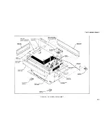
Страница 48: ...TM 11 6625 2850 14 P FIGURE 6 1 EXPLODED VIEW CABINET 6 9 ...
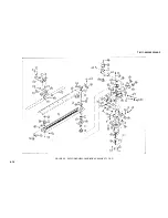
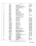
Страница 49: ...TM 11 6625 2850 14 P FIGURE 6 2 EXPLODED VIEW CARRIAGE ARM SHEET 1 OF 2 6 10 ...
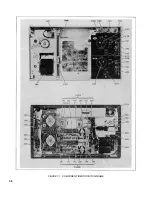
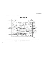
Страница 58: ...FIGURE 7 1 COMPONENT IDENTIFICATION FRAME 7 8 ...
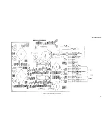
Страница 59: ...TM 11 6625 2850 14 P Figure 7 2 Component Identification Circuit Board 7 9 ...
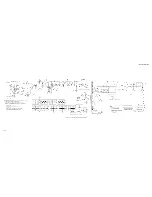
Страница 60: ...TM 11 6625 2850 14 P Figure 7 3 Schematic Model 7035B D 07035 92550 7 10 ...
Страница 62: ...TM 11 6625 2850 14 P FIGURE 8 1 COMPONENT IDENTIFICATION CIRCUIT BOARD 8 2 ...
Страница 66: ...TM 11 6625 2850 14 P FIGURE 8 5 EXPLODED VIEW CARRIAGE ARM 8 6 ...

