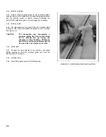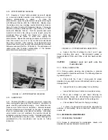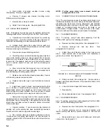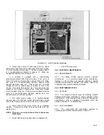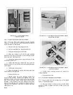
FIGURE 5-5. PEN SCALE REMOVAL
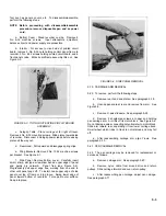
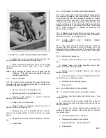
FIGURE 5-6. CARRIAGE ARM REMOVAL
5-23. POTENTIOMETER REPLACEMENT - X-AXIS
5-24. The mandrel and its mounting channel are an integral
unit, available only as a single item. Install as follows:
a.
Remove rear hood and platen. See paragraph 5-18.
b.
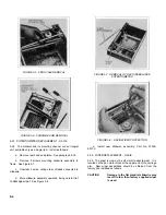
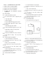
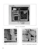
Remove 2 screws mounting slidewire assembly to
frame. See Figure 5-7.
c.
Unsolder 3 wires, noting order of leads connected to
slidewire.
d.
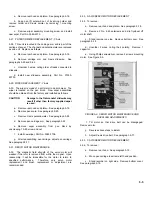
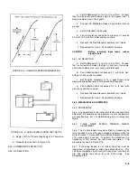
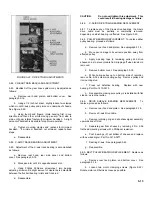
More slidewire assembly upwards, being careful
not
to damage wiper.
See Figure 5-8.
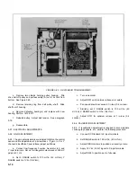
FIGURE 5-7. REMOVAL OF X-AXIS REBALANCE
POTENTIOMETER
FIGURE 5-8. X-AXIS WIPER PROTECTION
e.
Install new slidewire assembly, Part No. 07035-
80730.
5-25. WIPER REPLACEMENT - X-AXIS
5-26. The wiper is made of a soft metal to absorb wear. It is
located on the pen motor block at the upper end of the carriage
arm. New wiper assemblies should be obtained from the
factory and installed as follows:
CAUTION
Damage to the flat mandrel slidewire may
result if other than factory supplied wiper
is used.
5-4
Содержание HP-7035B
Страница 1: ...TECHNICAL MANUAL HEWLETT PACKARD MODEL HP 7035B ...
Страница 9: ...FIGURE 1 4 DIMENSION DRAWING FIGURE 1 5 ACCESSORIES 1 3 ...
Страница 12: ...FIGURE 1 7 TYPICAL FREQUENCY RESPONSE INPUT FILTER FIGURE 1 8 TYPICAL DYNAMIC RESPONSE 1 6 ...
Страница 14: ...FIGURE 2 1 WING BRACKET INSTALLATION FIGURE 2 2 STACKED CONFIGURATION 2 2 ...
Страница 16: ...FIGURE 3 1 FRONT PANEL CONTROLS 7035B AND 7035B 001 MODELS 3 2 ...
Страница 20: ...FIGURE 4 1 BLOCK DIAGRAM FIGURE 4 2 DETAILED BLOCK DIAGRAM 4 2 ...
Страница 48: ...TM 11 6625 2850 14 P FIGURE 6 1 EXPLODED VIEW CABINET 6 9 ...
Страница 49: ...TM 11 6625 2850 14 P FIGURE 6 2 EXPLODED VIEW CARRIAGE ARM SHEET 1 OF 2 6 10 ...
Страница 58: ...FIGURE 7 1 COMPONENT IDENTIFICATION FRAME 7 8 ...
Страница 59: ...TM 11 6625 2850 14 P Figure 7 2 Component Identification Circuit Board 7 9 ...
Страница 60: ...TM 11 6625 2850 14 P Figure 7 3 Schematic Model 7035B D 07035 92550 7 10 ...
Страница 62: ...TM 11 6625 2850 14 P FIGURE 8 1 COMPONENT IDENTIFICATION CIRCUIT BOARD 8 2 ...
Страница 66: ...TM 11 6625 2850 14 P FIGURE 8 5 EXPLODED VIEW CARRIAGE ARM 8 6 ...

