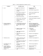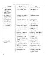
TABLE 7-1. 7035B TROUBLESHOOTING INDEX (Continued)
PROBLEM
POSSIBLE CAUSE
CURE
18.
(cont)
b.
Amplifier gain too low.
b.
Adjust amplifier gain
(see paragraph 5-92).
c.
Damping capacitor improper
c.
Replace capacitor. Increasing
value.
value decreases overshoot.
19.
Excessive X-axis over-
a.
Drive belt too loose. Measure
a.
Tighten drive belt
shoot.
per paragraph 5-78.
(paragraph 5-79).
b.
Amplifier gain too low.
b.
Adjust amplifier gain
(see paragraph 5-92).
c.
Damping capacitor improper
c.
Replace with proper value
value.
capacitor. Increasing
value decreases overshoot.
20.
X-axis produces loud, audible
X-axis backlash too loose or too
Adjust backlash (paragraph 5-83).
noise when moved fast.
tight.
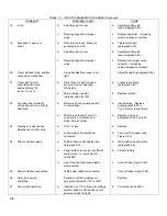
21.
Y-axis won't go full
a.
Drive string too tight, causing
a.
Loosen drive string
scale (stops short by
spring to be over-extended,
(paragraph 5-67).
approximately 1/16
hitting stop.
inch to 1/4 inch).
b.
Zero pot wiper resistor
b.
Replace resistor.
improper value (R-120).
22.
One axis runs erratically
a.
Motor brush not properly seated
a.
Inspect brush. Replace
at high speed in one or both
to commutator.
per paragraph 5-38 or
directions.
"run-in" motor to seat brush.
b.
Motor brush tends to "cock" in
b.
Replace motor per
one direction of rotation and
paragraphs 5-34 and 5-35.
binds in brush holder.
23.
Slewing one axis causes
a.
CR-111 open
a.
Replace.
disturbance on other axiis.
b.
Lucite tubes in photochopper
b.
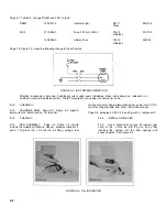
Cover with fish-paper (see
uncovered.
Figure 5-24).
24.
Paper holddown weak.
a.
Table surface contaminated (see
a.
Wash with soap and water
paragraph 5-9).
(paragraph 5-9).
b.
Paper surface too rough, insufficient
b.
Contact factory.
contact area (i.e., parchment or
curled film).
c.
One of the two table power leads
c.
Connect lead (Figure 5-24).
disconnected.
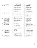
25.
Paper holddown inoperative.
Table power leads disconnected.
Connect leads (Figure 5-24).
26.
Servo gain varies
Excessive contact resistance in
Replace
erratically.
gain potentiometer R-137 or R-237.
27.
Very erratic operation.
a.
Operation on 115-volt line with voltage
a.
Correct switch position.
selector switch in 230 position (front
panel neon will not light).
7-6
Содержание HP-7035B
Страница 1: ...TECHNICAL MANUAL HEWLETT PACKARD MODEL HP 7035B ...
Страница 9: ...FIGURE 1 4 DIMENSION DRAWING FIGURE 1 5 ACCESSORIES 1 3 ...
Страница 12: ...FIGURE 1 7 TYPICAL FREQUENCY RESPONSE INPUT FILTER FIGURE 1 8 TYPICAL DYNAMIC RESPONSE 1 6 ...
Страница 14: ...FIGURE 2 1 WING BRACKET INSTALLATION FIGURE 2 2 STACKED CONFIGURATION 2 2 ...
Страница 16: ...FIGURE 3 1 FRONT PANEL CONTROLS 7035B AND 7035B 001 MODELS 3 2 ...
Страница 20: ...FIGURE 4 1 BLOCK DIAGRAM FIGURE 4 2 DETAILED BLOCK DIAGRAM 4 2 ...
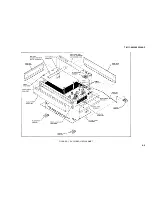
Страница 48: ...TM 11 6625 2850 14 P FIGURE 6 1 EXPLODED VIEW CABINET 6 9 ...
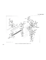
Страница 49: ...TM 11 6625 2850 14 P FIGURE 6 2 EXPLODED VIEW CARRIAGE ARM SHEET 1 OF 2 6 10 ...
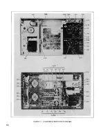
Страница 58: ...FIGURE 7 1 COMPONENT IDENTIFICATION FRAME 7 8 ...
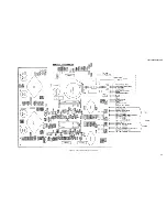
Страница 59: ...TM 11 6625 2850 14 P Figure 7 2 Component Identification Circuit Board 7 9 ...
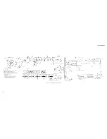
Страница 60: ...TM 11 6625 2850 14 P Figure 7 3 Schematic Model 7035B D 07035 92550 7 10 ...
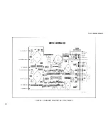
Страница 62: ...TM 11 6625 2850 14 P FIGURE 8 1 COMPONENT IDENTIFICATION CIRCUIT BOARD 8 2 ...
Страница 66: ...TM 11 6625 2850 14 P FIGURE 8 5 EXPLODED VIEW CARRIAGE ARM 8 6 ...

