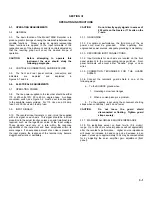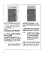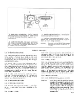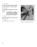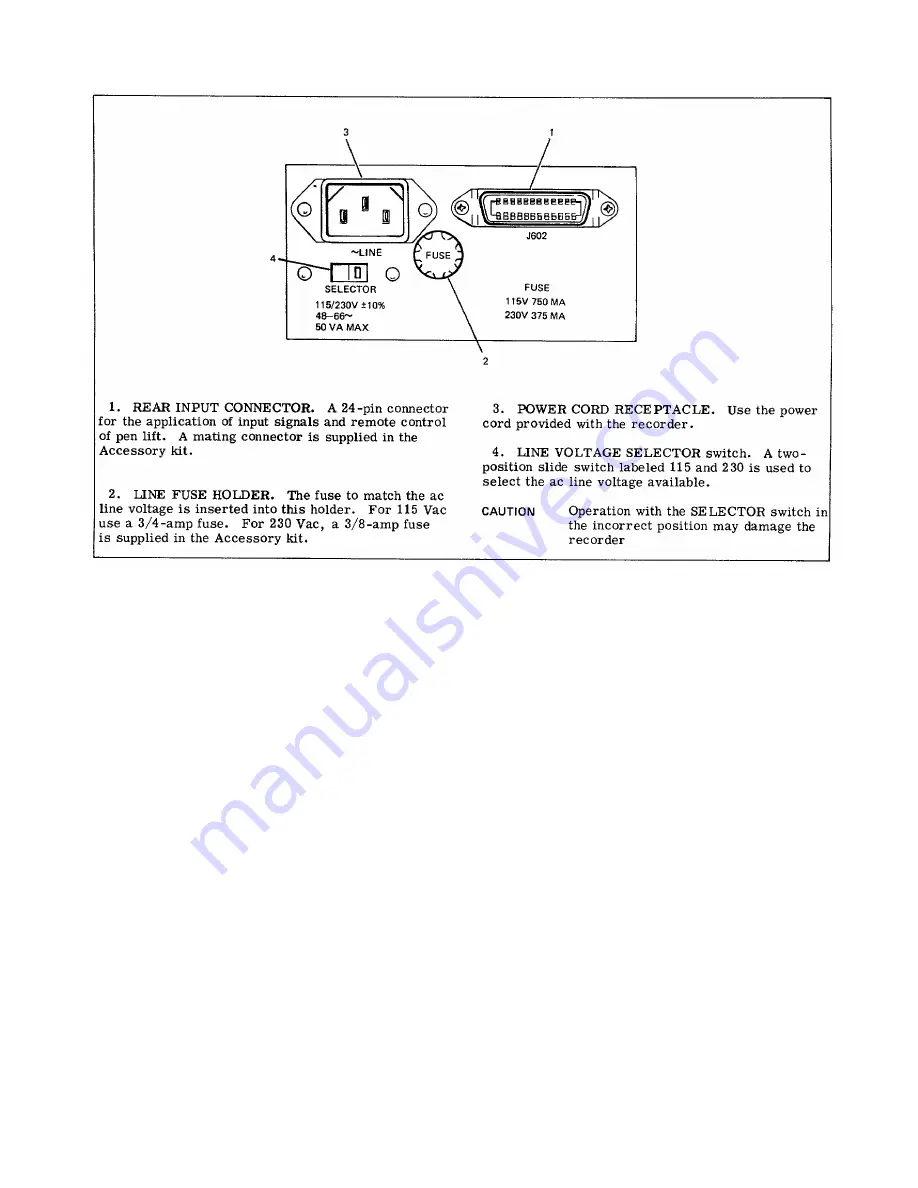
FIGURE 3-2. REAR PANEL
3-19. OPERATING PRECAUTIONS
3-20. The POWER/SERVO toggle switch apples 115 volts AC
to the recorder. To lower power dissipation and avoid
unnecessary wear to the balancing potentiometers and other
mechanical parts when not actually recording, place the toggle
switch to ON-OFF position.
3-21. When a voltage in excess of the RANGE SETTING is
applied to either set of input terminals, the carriage arm or pen
mount (depending upon the axis used) will be driven rapidly to
full scale and strike the stop. If this condition prevails, the
motor will continue running due to a slip-clutch arrangement,
prolonged running against the stop may cause excessive
motor heating and clutch wear.
3-22. Operation on the most sensitive input range with no
input (input terminals not connected) will result in an inaccurate
zero null. This can be overcome by shunting the input
terminals with a 20k (maximum resistor).
3-23. OPERATING INSTRUCTIONS
3-24. OPERATIONAL CONDITIONS
3-25. Amplitude of the signal must be within the scale range
and vary in level within the response capabilities of the
instrument.
3-26. CONNECT POWER
3-27. Set the power voltage selector switch located on rear of
instrument to either 115 or 230 volts, depending on the
available power source. Connect power cord between the
power receptacle and the power source.
3-28. CONNECT INPUTS
3-29. Connect the signal inputs to each axis through the front
input terminals using open wires or banana connectors, or
through the rear input connectors using the furnished mating
connector. Normally connect the guard input terminal to the
negative input terminal. However, if the shields are to be
driven directly from a remote common mode source, the
jumper is disconnected and a separate wire is connected
between the guard input and the common mode voltage
source. Set RANGE switch to the expected maximum values.
3-30. ENERGIZE RECORDER
3-31. Set the POWER/SERVO toggle switch to ON-ON.
CAUTION
Units using photochoppers require a few
minutes of operation to eliminate dark
storage effects. After prolonged storage
of 3 to 6 months, a longer period of run in
may be required. After several days of
storage, a slight improvement in retrace
characteristics may be produced by
several high speed full scale excursions
on each axis.
3-3
Содержание HP-7035B
Страница 1: ...TECHNICAL MANUAL HEWLETT PACKARD MODEL HP 7035B ...
Страница 9: ...FIGURE 1 4 DIMENSION DRAWING FIGURE 1 5 ACCESSORIES 1 3 ...
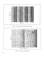
Страница 12: ...FIGURE 1 7 TYPICAL FREQUENCY RESPONSE INPUT FILTER FIGURE 1 8 TYPICAL DYNAMIC RESPONSE 1 6 ...
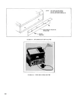
Страница 14: ...FIGURE 2 1 WING BRACKET INSTALLATION FIGURE 2 2 STACKED CONFIGURATION 2 2 ...
Страница 16: ...FIGURE 3 1 FRONT PANEL CONTROLS 7035B AND 7035B 001 MODELS 3 2 ...
Страница 20: ...FIGURE 4 1 BLOCK DIAGRAM FIGURE 4 2 DETAILED BLOCK DIAGRAM 4 2 ...
Страница 48: ...TM 11 6625 2850 14 P FIGURE 6 1 EXPLODED VIEW CABINET 6 9 ...
Страница 49: ...TM 11 6625 2850 14 P FIGURE 6 2 EXPLODED VIEW CARRIAGE ARM SHEET 1 OF 2 6 10 ...
Страница 58: ...FIGURE 7 1 COMPONENT IDENTIFICATION FRAME 7 8 ...
Страница 59: ...TM 11 6625 2850 14 P Figure 7 2 Component Identification Circuit Board 7 9 ...
Страница 60: ...TM 11 6625 2850 14 P Figure 7 3 Schematic Model 7035B D 07035 92550 7 10 ...
Страница 62: ...TM 11 6625 2850 14 P FIGURE 8 1 COMPONENT IDENTIFICATION CIRCUIT BOARD 8 2 ...
Страница 66: ...TM 11 6625 2850 14 P FIGURE 8 5 EXPLODED VIEW CARRIAGE ARM 8 6 ...

