SECTION V
MAINTENANCE, PERFORMANCE CHECKS, AND ADJUSTMENTS
5-1. INTRODUCTION
5-2. This section provides information for maintenance,
performance testing, functional checks, and adjustments of the
7035B X-Y Recorder. Maintenance procedures, tests, and
adjustments will ensure that the instrument conforms to
specifications. Functional checks maintain the instrument in an
operational condition. If the instrument fails to meet
specifications, or is inoperable, refer to Section VII,
Troubleshooting.
5-3.
PREVENTIVE MAINTENANCE
5-4.
GENERAL
5-5.
The instrument must be maintained properly for
accurate, trouble-free operation. This requires periodic
lubrication, performance checks, and visual and electrical
checks. In accordance with good maintenance procedures for
all precision measuring instruments, Hewlett-Packard
recorders should be protected from dust. Cover the instrument
when not in use.
5-6.
ENVIRONMENTAL OPERATION
5-7.
This instrument is designed to operate over an ambient
temperature range of approximately 0
°
C to 55
°
C. Operation
under other conditions will produce inaccurate results and may
cause damage to the recorder. In areas with high humidity,
graph paper may become distorted, affecting the accuracy of
the grid lines. The area of operation should also be as free as
possible of air contamination (soot, smoke, fumes, etc).
Excessive air contamination will require more frequent
cleaning.
5-8.
CLEANING
5-9.
Thorough cleaning should be performed periodically.
Intervals are determined by type of operation, local air
contamination, and climatic conditions. Generally, under
normal use and conditions, cleaning intervals should be nine to
twelve months. Cleaning routine should include the following:
a.
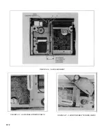
Remove platen and bottom cover. See paragraph
5-18.
b.
In accessible areas and where there is only dust
accumulation, cleaning can be accomplished with an air gun.
In more accessible areas and where the air gun will not
remove dirt, dust, or ink, accumulations should be removed
with a sponge or cloth saturated in plain soap and warm water,
then wiped dry.
c.
Every eighteen to twenty-four months, gears should
be cleaned thoroughly with a solvent and relubricated. Do not
use soap or water on these components.
d.
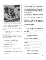
The following method is recommended for cleaning
Autogrip table. Dust and other accumulation of foreign films on
the table surface will lower the paper holding force. The film
may be removed and the table holding ability restored by using
the cleaning procedure. If strong chemicals, abrasives, or too
much water is used, the table may be permanently damaged.
To clean:
1.
Remove pen and paper from recorder.
2.
Select a mild liquid soap. Do not use products
with abrasive or corrosive chemicals.
3.
Use soft cloth that will not scratch the surface but
will absorb water.
4.
Saturate the cloth in warm, soapy water. Wring
cloth until majority of water has been removed.
5.
Wipe table surface with damp cloth until Autogrip
table is clean.
CAUTION
Never let water stand on Autogrip
surface. It may permanently damage the
table.
6.
Wipe any moisture from surface.
7.
Allow a few minutes to dry before recording.
CAUTION
Do not use solvents or silicone-based
cleaners of any type on the Autogrip
platen.
5-1
Содержание HP-7035B
Страница 1: ...TECHNICAL MANUAL HEWLETT PACKARD MODEL HP 7035B ...
Страница 9: ...FIGURE 1 4 DIMENSION DRAWING FIGURE 1 5 ACCESSORIES 1 3 ...
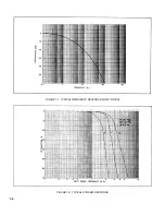
Страница 12: ...FIGURE 1 7 TYPICAL FREQUENCY RESPONSE INPUT FILTER FIGURE 1 8 TYPICAL DYNAMIC RESPONSE 1 6 ...
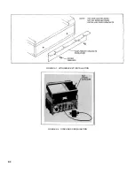
Страница 14: ...FIGURE 2 1 WING BRACKET INSTALLATION FIGURE 2 2 STACKED CONFIGURATION 2 2 ...
Страница 16: ...FIGURE 3 1 FRONT PANEL CONTROLS 7035B AND 7035B 001 MODELS 3 2 ...
Страница 20: ...FIGURE 4 1 BLOCK DIAGRAM FIGURE 4 2 DETAILED BLOCK DIAGRAM 4 2 ...
Страница 48: ...TM 11 6625 2850 14 P FIGURE 6 1 EXPLODED VIEW CABINET 6 9 ...
Страница 49: ...TM 11 6625 2850 14 P FIGURE 6 2 EXPLODED VIEW CARRIAGE ARM SHEET 1 OF 2 6 10 ...
Страница 58: ...FIGURE 7 1 COMPONENT IDENTIFICATION FRAME 7 8 ...
Страница 59: ...TM 11 6625 2850 14 P Figure 7 2 Component Identification Circuit Board 7 9 ...
Страница 60: ...TM 11 6625 2850 14 P Figure 7 3 Schematic Model 7035B D 07035 92550 7 10 ...
Страница 62: ...TM 11 6625 2850 14 P FIGURE 8 1 COMPONENT IDENTIFICATION CIRCUIT BOARD 8 2 ...
Страница 66: ...TM 11 6625 2850 14 P FIGURE 8 5 EXPLODED VIEW CARRIAGE ARM 8 6 ...

