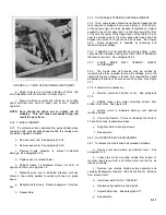
FIGURE 4-3. RANGE SELECTOR
When the Range selector is set to any of the vernier positions
the resistors used in the fixed positions are switched out and
replaced by a new set of components. The heart of the vernier
circuitry is the variable potentiometer R-108 and the voltage
limiter R-110. When the range selector is set to the first
vernier range, the input signal is applied directly to R-108 and
R-110, and passed through the wiper to the balance circuit.
The other four positions use R-107 or R-106 to attenuate the
signal. In the last two positions the signal from the wiper of R-
108 is divided by the string composed of R-111,
R-112, and R-113.
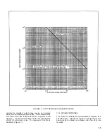
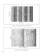
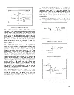
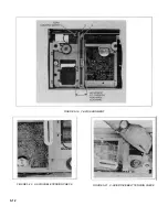
4-11. INPUT FILTER (See Figure 4-4.) The input filter is
composed of 3 RC sections. It is a low pass filter providing a
minimum of 20 db attenuation of 60 Hz and a cutoff of 18 db
per octave above 60 Hz to insure smooth plotting from signals
containing extraneous noise. Filter components in the Y axis
are capacitors C-103, C-104, and C-105, with resistors R-114,
R-115, and R-116. The insertion of a filter of this type in each
axis of a two-axis recorder can cause phase shift relative to the
other axis. Since this phase shift can vary from unit to unit
(depending upon component tolerances). R-114 is a variable
resistor that is factory adjusted to equalize the phase shift
between axes. A slight phase shift, however, will be noted
when changing from range to range and when using the range
selector vernier. This phase shift may become very
pronounced on the 1 mv/inch (0.4 mv/cm) range if the input
source impedance is extremely large or extremely small.
Diodes CR-101 and CR-102 are protective devices used to
minimize the possibility of component damage due to an over-
voltage at the input terminals.
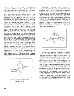
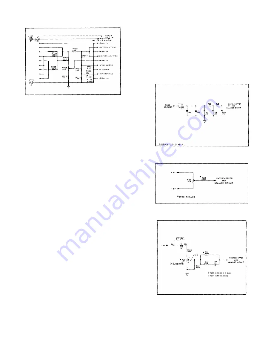
4-12. ZERO CIRCUIT (See Figure 4-5.) The zero circuit is
composed of R-123 and R-120. The potentiometer R-123
permits the electrical zero to be placed ±1 full scale from
normal zero. Resistor R-120 limits the voltage that is applied
to the Photochopper and Balance Circuit.
4-13. SLIDEWIRE CIRCUIT (See Figure 4-6.) The Slidewire
Circuit provides the electrical feedback to the Photochopper
and Balance Circuit from the pen carriage or carriage arm.
Resistors R-126 and R-125 are calibration resistors for the
feedback element (slidewire) R-124. Capacitor C-108 passes
unwanted spurious wiper noise to circuit common. Resistor
R-121 limits the voltage applied to the Photochopper and
Balance Circuit.
4-14. DAMPING NETWORK (See Figure 4-6). The phase
lead network (C-107 and R-122) draws a charging current
FIGURE 4-4. INPUT FILTER
FIGURE 4-5. ZERO CIRCUIT
FIGURE 4-6. SLIDEWIRE AND DAMPING CIRCUIT
4-3
Содержание HP-7035B
Страница 1: ...TECHNICAL MANUAL HEWLETT PACKARD MODEL HP 7035B ...
Страница 9: ...FIGURE 1 4 DIMENSION DRAWING FIGURE 1 5 ACCESSORIES 1 3 ...
Страница 12: ...FIGURE 1 7 TYPICAL FREQUENCY RESPONSE INPUT FILTER FIGURE 1 8 TYPICAL DYNAMIC RESPONSE 1 6 ...
Страница 14: ...FIGURE 2 1 WING BRACKET INSTALLATION FIGURE 2 2 STACKED CONFIGURATION 2 2 ...
Страница 16: ...FIGURE 3 1 FRONT PANEL CONTROLS 7035B AND 7035B 001 MODELS 3 2 ...
Страница 20: ...FIGURE 4 1 BLOCK DIAGRAM FIGURE 4 2 DETAILED BLOCK DIAGRAM 4 2 ...
Страница 48: ...TM 11 6625 2850 14 P FIGURE 6 1 EXPLODED VIEW CABINET 6 9 ...
Страница 49: ...TM 11 6625 2850 14 P FIGURE 6 2 EXPLODED VIEW CARRIAGE ARM SHEET 1 OF 2 6 10 ...
Страница 58: ...FIGURE 7 1 COMPONENT IDENTIFICATION FRAME 7 8 ...
Страница 59: ...TM 11 6625 2850 14 P Figure 7 2 Component Identification Circuit Board 7 9 ...
Страница 60: ...TM 11 6625 2850 14 P Figure 7 3 Schematic Model 7035B D 07035 92550 7 10 ...
Страница 62: ...TM 11 6625 2850 14 P FIGURE 8 1 COMPONENT IDENTIFICATION CIRCUIT BOARD 8 2 ...
Страница 66: ...TM 11 6625 2850 14 P FIGURE 8 5 EXPLODED VIEW CARRIAGE ARM 8 6 ...

