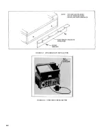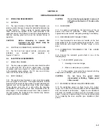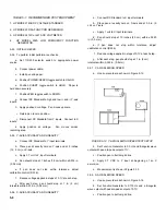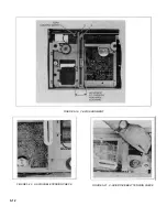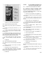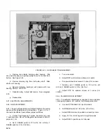
5-10. POTENTIOMETER CLEANING
5-11. Irregular or "jumpy" plots produced by smooth signals
on a properly adjusted recorder may indicate worn or dirty
balance potentiometers or wipers. To clean the
potentiometer., spray the potentiometer along its entire length
with Slidewire Cleaner (Part No. 5080-3605). Rapidly move
the carriage arm or pen carriage several full scale excursions.
Spray the wiper directly with Slideware Cleaner. Thoroughly
saturate a Kimwipe (Kimberly-Clark Type 900-S) or a cotton
swab with Slidewire Cleaner. Rub the potentiometer (wire
mandrel and return strip) along its entire length, using the
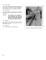
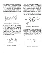
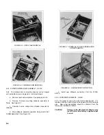
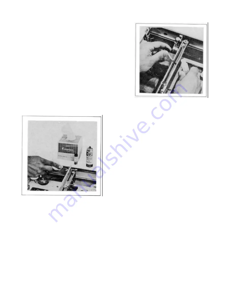
moistened tissue or swab (see Figure 5-1). Note any
discoloration of the tissue or swab after rubbing the
potentiometer. Repeat the cleaning procedure until there is no
stain, then clean once more to insure that all contaminants
have been removed. After cleaning, the potentiometer (wire
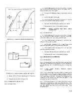
mandrel and return strip) must be lubricated with the furnished
Slidewire Lubricant (Part No. 5080-3635). This lubrication will
reduce wear and chemical contamination of the balance
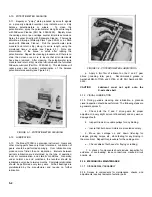
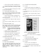
potentiometer assembly (see Figure 5-2).
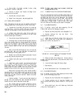
FIGURE 5-1. POTENTIOMETER CLEANING
5-12. LUBRICATION
5-13. The Model 7035B is a precision instrument. Gears and
other moving parts have very close tolerances. Lubrication of
gears should be performed sparingly. Over lubrication may
produce more friction than no lubrication. Intervals between
periodic lubrication are determined by the type of operation,
local air contamination, and climatic conditions. Generally,
under normal use and conditions, the recorder should be
lubricated every nine to twelve months. Complete relubrication
should be performed every two years. All ball bearings are
prelubricated by the manufacturer and require no further
lubrication.
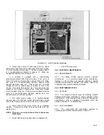
FIGURE 5-2. POTENTIOMETER LUBRICATION
a.
Apply a thin film of lubricant on the X and Y gear
drives (including idler gear). Recommended grease is
Aeroshell MIL-G-7118A and 3276A or HP Part Number 6040-
0222.
CAUTION
Lubricant must not spill onto the
X-axis drive belt.
5-14. VISUAL LUBRICATION
5-15. During periodic cleaning and lubrication, a planned
visual inspection should be performed. The following steps are
a general approach:
a.
Check both the X and Y drive gears for proper
adjustment (a very slight amount of backlash) and any worn or
damaged teeth.
b.
Inspect X-axis drive cable pulleys for any binding.
c.
Insure that both servo motors are mounted securely.
d.
Move pen carriage up and down, listening for
scrapes, grinding noises, etc., while feeling for any binding in
the movement. Repeat this procedure for the carriage arm.
e.
Check cables of both axes for fraying or rubbing.
f.
A check of components should include inspection for
evidence of overheating, loose connections, cracked circuit
boards, etc.
5-16. MECHANICAL MAINTENANCE
5-17. DISASSEMBLY/ASSEMBLY
5-18. Access to components for maintenance, checks, and
adjustments requires removal of exterior parts
5-2
Содержание HP-7035B
Страница 1: ...TECHNICAL MANUAL HEWLETT PACKARD MODEL HP 7035B ...
Страница 9: ...FIGURE 1 4 DIMENSION DRAWING FIGURE 1 5 ACCESSORIES 1 3 ...
Страница 12: ...FIGURE 1 7 TYPICAL FREQUENCY RESPONSE INPUT FILTER FIGURE 1 8 TYPICAL DYNAMIC RESPONSE 1 6 ...
Страница 14: ...FIGURE 2 1 WING BRACKET INSTALLATION FIGURE 2 2 STACKED CONFIGURATION 2 2 ...
Страница 16: ...FIGURE 3 1 FRONT PANEL CONTROLS 7035B AND 7035B 001 MODELS 3 2 ...
Страница 20: ...FIGURE 4 1 BLOCK DIAGRAM FIGURE 4 2 DETAILED BLOCK DIAGRAM 4 2 ...
Страница 48: ...TM 11 6625 2850 14 P FIGURE 6 1 EXPLODED VIEW CABINET 6 9 ...
Страница 49: ...TM 11 6625 2850 14 P FIGURE 6 2 EXPLODED VIEW CARRIAGE ARM SHEET 1 OF 2 6 10 ...
Страница 58: ...FIGURE 7 1 COMPONENT IDENTIFICATION FRAME 7 8 ...
Страница 59: ...TM 11 6625 2850 14 P Figure 7 2 Component Identification Circuit Board 7 9 ...
Страница 60: ...TM 11 6625 2850 14 P Figure 7 3 Schematic Model 7035B D 07035 92550 7 10 ...
Страница 62: ...TM 11 6625 2850 14 P FIGURE 8 1 COMPONENT IDENTIFICATION CIRCUIT BOARD 8 2 ...
Страница 66: ...TM 11 6625 2850 14 P FIGURE 8 5 EXPLODED VIEW CARRIAGE ARM 8 6 ...

