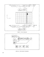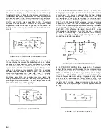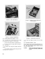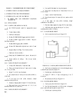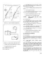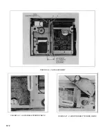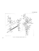
FIGURE 5-15. Y-AXIS DRIVE STRING
TENSION CHECK
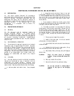
5-68. Y GEAR TRAIN BACKLASH ADJUSTMENT
5-69. The Y-axis drive system alignment requires adjusting
two gears. These two gears must be adjusted for backlash in
proper sequence for best results.
a.
Remove rear hood. See paragraph 5-18.
b.
Remove rear side panel. See paragraph 5-18.
c.
Snap pen lift solenoid out of its holder.
d.
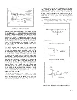
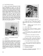
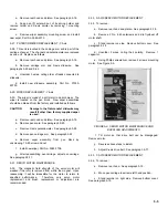
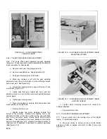
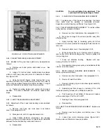
Move pen carriage to left until the gear adjusting
setscrew at rear of pen motor block is in line with large access
hole in rear wall. See Figure 5-16.
e.
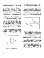
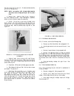
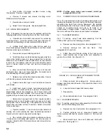
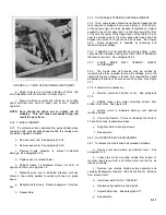
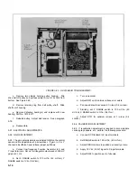
Loosen gear locking screw in upper left corner of pen
motor block (Figure 5-17).
f.
Lightly push idler gear toward pen drive, and turn
adjusting screw in or out to attain minimum backlash between
two set gears.
g.
Tighten gear locking screw.
h.
Move pen carriage to extreme left-hand position and
stand recorder on its right side.
i.
Remove bottom cover.
j.
Slightly loosen two motor clamping screws from
bottom of the recorder. Rotate motor slightly, first in one
direction and then in the other, while moving pen gear back
and forth until motor pinion rotates freely with minimum
backlash. This procedure varies mesh between motor pinion
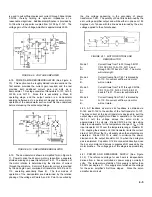
and pen drive gear due to an eccentric mounting shoulder. A
slight amount of backlash is desirable for optimum operation
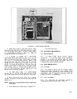
(See Figure 5-18).
FIGURE 5-16. Y-AXIS BACKLASH ADJUSTMENT (GEAR
ADJUSTING SCREW)
FIGURE 5-17. Y-AXIS BACKLASH ADJUSTMENT (GEAR
LOCKING SCREW)
k.
Tighten motor clamping screws and recheck for
optimum backlash.
l.
Reassemble recorder.
5-70. Y-AXIS PEN CARRIAGE ADJUSTMENT
5-71. The pen block rolls in the carriage arm on four plastic
rollers. To adjust these rollers:
a.
Move pen block to bottom of arm so 2-56 Bristol
setscrew in block is aligned with notch in side of arm, see
Figure 5-18.
5-10
Содержание HP-7035B
Страница 1: ...TECHNICAL MANUAL HEWLETT PACKARD MODEL HP 7035B ...
Страница 9: ...FIGURE 1 4 DIMENSION DRAWING FIGURE 1 5 ACCESSORIES 1 3 ...
Страница 12: ...FIGURE 1 7 TYPICAL FREQUENCY RESPONSE INPUT FILTER FIGURE 1 8 TYPICAL DYNAMIC RESPONSE 1 6 ...
Страница 14: ...FIGURE 2 1 WING BRACKET INSTALLATION FIGURE 2 2 STACKED CONFIGURATION 2 2 ...
Страница 16: ...FIGURE 3 1 FRONT PANEL CONTROLS 7035B AND 7035B 001 MODELS 3 2 ...
Страница 20: ...FIGURE 4 1 BLOCK DIAGRAM FIGURE 4 2 DETAILED BLOCK DIAGRAM 4 2 ...
Страница 48: ...TM 11 6625 2850 14 P FIGURE 6 1 EXPLODED VIEW CABINET 6 9 ...
Страница 49: ...TM 11 6625 2850 14 P FIGURE 6 2 EXPLODED VIEW CARRIAGE ARM SHEET 1 OF 2 6 10 ...
Страница 58: ...FIGURE 7 1 COMPONENT IDENTIFICATION FRAME 7 8 ...
Страница 59: ...TM 11 6625 2850 14 P Figure 7 2 Component Identification Circuit Board 7 9 ...
Страница 60: ...TM 11 6625 2850 14 P Figure 7 3 Schematic Model 7035B D 07035 92550 7 10 ...
Страница 62: ...TM 11 6625 2850 14 P FIGURE 8 1 COMPONENT IDENTIFICATION CIRCUIT BOARD 8 2 ...
Страница 66: ...TM 11 6625 2850 14 P FIGURE 8 5 EXPLODED VIEW CARRIAGE ARM 8 6 ...

