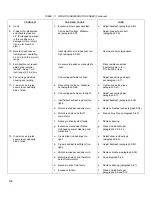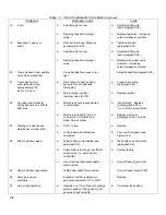
TABLE 7-1. 7035B TROUBLESHOOTING INDEX (Continued)
PROBLEM
POSSIBLE CAUSE
CURE
27.
(cont)
b.
Bearing in drive train faulty.
b.
Replace bearing
(paragraph 5-87).
c.
Motor brushes excessively
c.
Replace brushes (see
worn.
paragraph 5-38).
d.
Motor brush stuck, held off
d.
See paragraph 5-39.
commutator.
e.
Excessive friction.
e.
Clean and lubricate per
paragraphs 5-9 and 5-12.
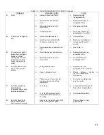
28.
Common mode rejection
a.
Guard strap disconnected.
a.
Connect strap.
poor.
b.
Guard not connected directly
b.
Remove guard strap and
to common mode source.
connect guard input to
source.
c.
Source impedance unbalance too
c.
See Table 1-1.
high.
29.
One axis motor will hot
a.
Motor brushes excessively worn,
a.
Replace brushes (see
respond to input signal.
paragraph 5-38).
(Gears and motor
mechanically free and
b.
Motor brush stuck, held off
b.
Free-up brush (see
electronics providing
commutator.
paragraph 5-39).
proper drive signal to
motor).
30.
Recorder dives hard to
a.
Faulty slidewire wiper.
a.
Replace wiper (see
end of scale, will not
paragraphs 5-26 and 5-30).
balance.
b.
Open In balance circuit.
b.
Check balance circuits in
fig. 7-3 to locate faulty
components.
c.
Phase reversal in servo system
c.
Correct by reversing wires
(common occurrence during
on servo motor.
repair work).
31.
Recorder completely
a.
Fuse blown.
a.
Locate and correct cause of
dead (Autogrip
blown fuse. Replace fuse.
inoperative, power neon
indicator inoperative).
b.
115 volt/230 volt switch in 230
b.
Correct switch position.
volt position when powered on
115 volts.
32.
Recorder dead (Auto-
Neon bulbs in photochopper not lit.
Check voltages in neon
grip operates, power
Fault in neon power supply.
power supply.
neon indicator operates).
7-7
Содержание HP-7035B
Страница 1: ...TECHNICAL MANUAL HEWLETT PACKARD MODEL HP 7035B ...
Страница 9: ...FIGURE 1 4 DIMENSION DRAWING FIGURE 1 5 ACCESSORIES 1 3 ...
Страница 12: ...FIGURE 1 7 TYPICAL FREQUENCY RESPONSE INPUT FILTER FIGURE 1 8 TYPICAL DYNAMIC RESPONSE 1 6 ...
Страница 14: ...FIGURE 2 1 WING BRACKET INSTALLATION FIGURE 2 2 STACKED CONFIGURATION 2 2 ...
Страница 16: ...FIGURE 3 1 FRONT PANEL CONTROLS 7035B AND 7035B 001 MODELS 3 2 ...
Страница 20: ...FIGURE 4 1 BLOCK DIAGRAM FIGURE 4 2 DETAILED BLOCK DIAGRAM 4 2 ...
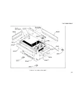
Страница 48: ...TM 11 6625 2850 14 P FIGURE 6 1 EXPLODED VIEW CABINET 6 9 ...
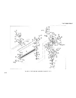
Страница 49: ...TM 11 6625 2850 14 P FIGURE 6 2 EXPLODED VIEW CARRIAGE ARM SHEET 1 OF 2 6 10 ...
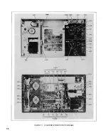
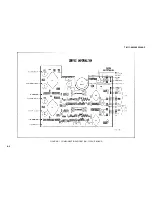
Страница 58: ...FIGURE 7 1 COMPONENT IDENTIFICATION FRAME 7 8 ...
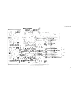
Страница 59: ...TM 11 6625 2850 14 P Figure 7 2 Component Identification Circuit Board 7 9 ...
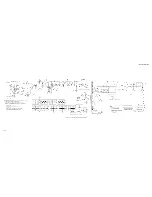
Страница 60: ...TM 11 6625 2850 14 P Figure 7 3 Schematic Model 7035B D 07035 92550 7 10 ...
Страница 62: ...TM 11 6625 2850 14 P FIGURE 8 1 COMPONENT IDENTIFICATION CIRCUIT BOARD 8 2 ...
Страница 66: ...TM 11 6625 2850 14 P FIGURE 8 5 EXPLODED VIEW CARRIAGE ARM 8 6 ...

