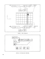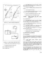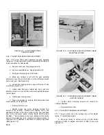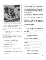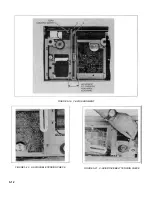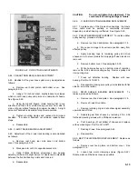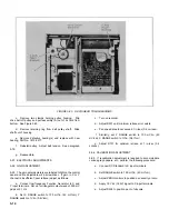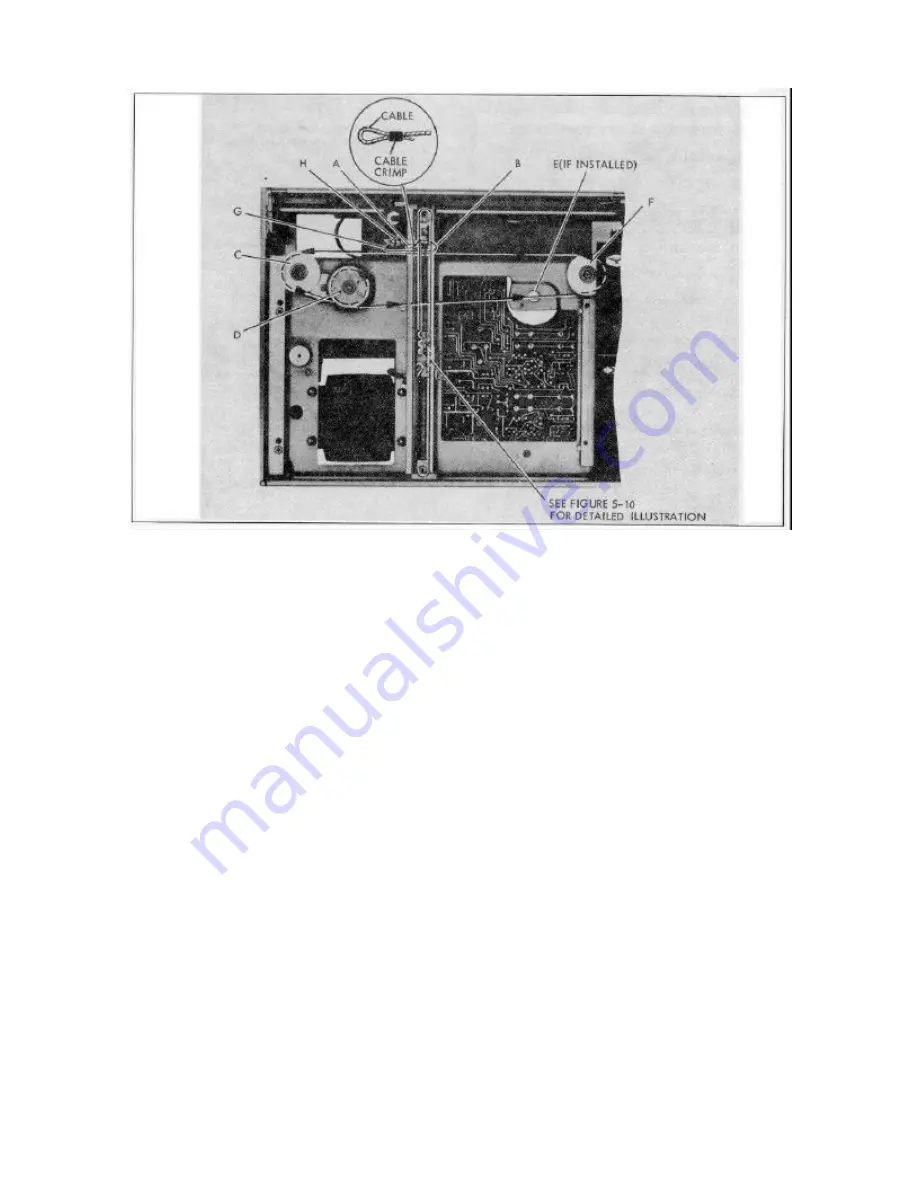
FIGURE 5-11. RESTRINGING DIAGRAM
d.
Attach loop to center of cable yoke (Point A). Route
cable around right-hand side of cable yoke (Point B), and pass
it in front of cable yoke to pulley C. Continue around pulley C
in a counterclockwise direction to sheave D. Make one
counterclockwise turn around sheave D.
e.
If recorder is equipped with a retransmitting
potentiometer (Option 003) follow this step. If not, go on to
step f. From sheave D start cable in center of sheave E. Make
two turns in a counterclockwise direction, passing cable
beneath itself after each turn. After second turn run cable
through the slot on bottom edge of sheave to hole in the
sheave. Run cable through the hole, and under screw and
washer on top of sheave. Tighten screw. Pass cable through
slot on top edge of sheave. Continue around sheave two more
turns in a counterclockwise direction, passing each turn
beneath itself, and continue to pulley F.
f.
Pull cable around pulley F in counterclockwise
direction, pass it in front and around left-hand edge of cable
yoke (Point G) and pass it to screw (Point H) on Y motor block.
g.
Pass cable around screw (Point H) in clockwise
direction. Firmly pull on cable (to keep the cable taut), and
tighten screw.
NOTE: There is a nut on the bottom of Nut H. Make sure
this is tight.
h.
Check cable tension as described in paragraph 5-75.
i.
Clip off the excess wire.
5-45. ELECTRICAL MAINTENANCE
5-46. REQUIREMENTS
5-47. The Model 7035B requires minimum electrical
maintenance. It is carefully aligned during manufacture.
However, if the recorder ever requires alignment, specific
adjustment procedures are detailed in this section. Section VII,
Troubleshooting, contains additional material.
5-48. PERFORMANCE TESTS
5-49. CRITERIA
5-50. This instrument should meet the following Hewlett-
Packard performance standards to assure operation within
specifications. If this instrument fails to meet the following test
specifications, refer to adjustment procedures within this
section or Section VI, Troubleshooting.
5-51. TEST EQUIPMENT
5-52. The instruments and accessories required for
completing performance tests are listed in Table 5-1.
5-7
Содержание HP-7035B
Страница 1: ...TECHNICAL MANUAL HEWLETT PACKARD MODEL HP 7035B ...
Страница 9: ...FIGURE 1 4 DIMENSION DRAWING FIGURE 1 5 ACCESSORIES 1 3 ...
Страница 12: ...FIGURE 1 7 TYPICAL FREQUENCY RESPONSE INPUT FILTER FIGURE 1 8 TYPICAL DYNAMIC RESPONSE 1 6 ...
Страница 14: ...FIGURE 2 1 WING BRACKET INSTALLATION FIGURE 2 2 STACKED CONFIGURATION 2 2 ...
Страница 16: ...FIGURE 3 1 FRONT PANEL CONTROLS 7035B AND 7035B 001 MODELS 3 2 ...
Страница 20: ...FIGURE 4 1 BLOCK DIAGRAM FIGURE 4 2 DETAILED BLOCK DIAGRAM 4 2 ...
Страница 48: ...TM 11 6625 2850 14 P FIGURE 6 1 EXPLODED VIEW CABINET 6 9 ...
Страница 49: ...TM 11 6625 2850 14 P FIGURE 6 2 EXPLODED VIEW CARRIAGE ARM SHEET 1 OF 2 6 10 ...
Страница 58: ...FIGURE 7 1 COMPONENT IDENTIFICATION FRAME 7 8 ...
Страница 59: ...TM 11 6625 2850 14 P Figure 7 2 Component Identification Circuit Board 7 9 ...
Страница 60: ...TM 11 6625 2850 14 P Figure 7 3 Schematic Model 7035B D 07035 92550 7 10 ...
Страница 62: ...TM 11 6625 2850 14 P FIGURE 8 1 COMPONENT IDENTIFICATION CIRCUIT BOARD 8 2 ...
Страница 66: ...TM 11 6625 2850 14 P FIGURE 8 5 EXPLODED VIEW CARRIAGE ARM 8 6 ...

