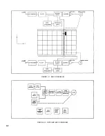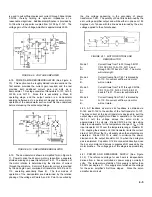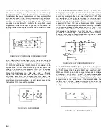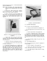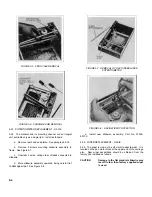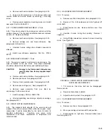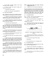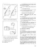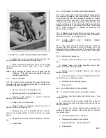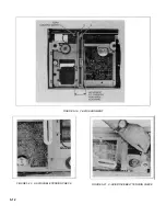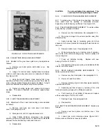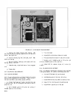
FIGURE 5-13. SLEWING SPEED DETERMINATION
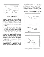
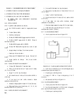
FIGURE 5-14. X-AXIS SLEWING SPEED TEST SETUP
d.
Apply 1 VDC to X input at beginning of a Y excursion.
e.
Measurement is shown in Figure 5-13.
5-59. COMMON MODE REJECTION
5-60. DC REJECTION
a.
Set RANGE switch to 1 mV/in. (0.4 mV/cm). Connect
input terminals with short between high (+) and guard, and 1K
Resistor between low (-) and guard.
b.
Connect DC Standard between Y guard terminal and
ground.
c.
Set DC Standard to 500 volts.
d.
Pen will overshoot and settle to a level not It exceed
0.16 inch (4.0 mm) from initial position on chart.
e.
Repeat at all fixed attenuator positions for Y inputs.
f.
Repeat test for X-axis. Pen deflection is same.
CAUTION
Before removing input leads, reduce
signal to zero.
5-61. AC REJECTION
a.
Set RANGE switch to 1 mV/in. (0.4 mV/cm). Connect
the 1k ohm resistor between the high (+) and low (-) terminals,
and a short between the low (-) and guard terminals.
b.
Pen deflection shall not exceed 0.1 inch (2.54 mm)
with pen in any position on paper.
c.
Set Function Generator to 10 V peak-to-peak sine
wave and sweep frequency ±3 Hz around line frequency.
d.
Pen deflection shall not exceed 0.2 in. (5 mm) with
pen at any position on paper.
e.
Repeat at all fixed attenuator positions for Y inputs.
f.
Repeat test for X-axis. Pen deflection is same.
5-62. MECHANICAL ADJUSTMENTS
5-63. PROCEDURE
5-64. Any adjustment to the instrument is deemed necessary
only when it is determined the instrument is out of adjustment
per specifications, but not malfunctioning due to component
failure.
5-65.
Y-AXIS DRIVE STRING TENSION CHECK/
ADJUSTMENT
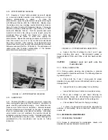
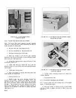
5-66. The Y cable tension may be verified by measuring the
force required to move the pen carriage downscale while the
motor is locked. This required force shall be between the limits
of 6 ounces and 12 ounces. To perform the procedure, it is
necessary to first remove be rear hood and platen. The
procedure is shown in Figure 5-15.
5-67. If the string tension is not correct, the string must be
lengthened or shortened to attain the desired tension. This
can be accomplished by removing the pen block from the pen
arm and retying the knot on the end of the string. See
paragraph 5-42.
5-9
Содержание HP-7035B
Страница 1: ...TECHNICAL MANUAL HEWLETT PACKARD MODEL HP 7035B ...
Страница 9: ...FIGURE 1 4 DIMENSION DRAWING FIGURE 1 5 ACCESSORIES 1 3 ...
Страница 12: ...FIGURE 1 7 TYPICAL FREQUENCY RESPONSE INPUT FILTER FIGURE 1 8 TYPICAL DYNAMIC RESPONSE 1 6 ...
Страница 14: ...FIGURE 2 1 WING BRACKET INSTALLATION FIGURE 2 2 STACKED CONFIGURATION 2 2 ...
Страница 16: ...FIGURE 3 1 FRONT PANEL CONTROLS 7035B AND 7035B 001 MODELS 3 2 ...
Страница 20: ...FIGURE 4 1 BLOCK DIAGRAM FIGURE 4 2 DETAILED BLOCK DIAGRAM 4 2 ...
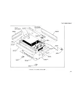
Страница 48: ...TM 11 6625 2850 14 P FIGURE 6 1 EXPLODED VIEW CABINET 6 9 ...
Страница 49: ...TM 11 6625 2850 14 P FIGURE 6 2 EXPLODED VIEW CARRIAGE ARM SHEET 1 OF 2 6 10 ...
Страница 58: ...FIGURE 7 1 COMPONENT IDENTIFICATION FRAME 7 8 ...
Страница 59: ...TM 11 6625 2850 14 P Figure 7 2 Component Identification Circuit Board 7 9 ...
Страница 60: ...TM 11 6625 2850 14 P Figure 7 3 Schematic Model 7035B D 07035 92550 7 10 ...
Страница 62: ...TM 11 6625 2850 14 P FIGURE 8 1 COMPONENT IDENTIFICATION CIRCUIT BOARD 8 2 ...
Страница 66: ...TM 11 6625 2850 14 P FIGURE 8 5 EXPLODED VIEW CARRIAGE ARM 8 6 ...

