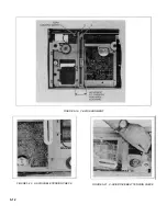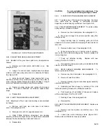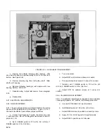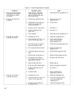
FIGURE 5-22. DRIVE TRAIN ADJUSTMENTS
5-82. X GEAR TRAIN BACKLASH ADJUSTMENT
5-83. Backlash of the gear drive system may be adjusted as
follows:
a.
Remove rear hood, platen, and bottom cover. See
paragraph 5-18.
b.
Using a 1/4 inch nut driver, slightly loosen two clamps
which mount X-axis pulley and pinion on underside of chassis.
See Figure 5-22.
c.
Using thumb and fingers, rotate housing first in one
direction and then other, while moving pen arm from side to
side, until gear rotates freely with minimum backlash. A slight
amount of backlash is desirable for optimum operation.
d.
Tighten mounting clamps and recheck for minimum
backlash. If minimum backlash not attained, repeat above
steps.
e.
Reassemble.
5-84. X-AXIS TRACK BEARING ADJUSTMENT
5-85. Adjustment of the X-axis track bearing is accomplished
as follows:
a.
Remove rear hood, rear side panel, and bottom
cover. See paragraph 5-18.
b.
Move pen arm until it is opposite access slot.
c.
Using Phillips Pozidrive screwdriver, turn bearing
adjusting screw until a slight amount of clearance is detectable
between the five ball bearing rollers and track rod.
d.
Reassemble.
CAUTION
Do not overtighten this adjustment. This
could result in bearing damage or failure.
5-86.
X-AXIS DRIVE TRAIN BEARING REPLACEMENT
5-87. To replace any of the X-axis drive bearings, the X-axis
drive cable must be partially or completely removed,
depending on which bearing is affected. See Figure 5-23.
5-88. PULLEY BEARING REPLACEMENT. To replace either
pulley bearing, proceed as follows:
a.
Remove rear hood and platen. See paragraph 5-18.
b.
Move pen carriage to its extreme position away from
affected pulley.
c.
Apply masking tape to remaining pulley and drive
sheave so as to prevent cable from slipping off when tension is
removed.
d.
Remove bottom cover. See paragraph 5-18.
e.
While holing pulley nut on bottom side of recorder,
remove No. 6-32 screw mounting pulley. Remove pulley and
its mounting stud.
f.
Press out defective bearing. Replace with new
bearing, Part No. 1410-0215.
g.
Reassemble, making sure pulley is reinstalled with flat
side up, as is other pulley.
5-89. DRIVE SHEAVE BEARING REPLACEMENT. To
replace, proceed as follows:
a.
Remove rear hood and platen. See paragraph 5-18.
b.
Remove X-axis drive cable.
c.
Remove retaining ring and slip sheave/gear assembly
upwards and off stud.
d.
Separate gear from sheave by removing 2 No. 2-56
flat head mounting screws with a Phillips screwdriver.
e.
Push bearings (2) out bottom of sheave and replace
with new bearing(s), Part No. 1410-0277.
f.
Restring X-axis. See paragraph 5-44.
g.
Reassemble.
5-90. BELT PULLEY BEARING REPLACEMENT. Replace as
follows:
a.
Remove rear hood, platen, and bottom cover. See
paragraph 5-18.
b.
Loosen two motor clamping screws (Figure 5-22).
Rotate motor until belt is as loose as possible.
5-13
Содержание HP-7035B
Страница 1: ...TECHNICAL MANUAL HEWLETT PACKARD MODEL HP 7035B ...
Страница 9: ...FIGURE 1 4 DIMENSION DRAWING FIGURE 1 5 ACCESSORIES 1 3 ...
Страница 12: ...FIGURE 1 7 TYPICAL FREQUENCY RESPONSE INPUT FILTER FIGURE 1 8 TYPICAL DYNAMIC RESPONSE 1 6 ...
Страница 14: ...FIGURE 2 1 WING BRACKET INSTALLATION FIGURE 2 2 STACKED CONFIGURATION 2 2 ...
Страница 16: ...FIGURE 3 1 FRONT PANEL CONTROLS 7035B AND 7035B 001 MODELS 3 2 ...
Страница 20: ...FIGURE 4 1 BLOCK DIAGRAM FIGURE 4 2 DETAILED BLOCK DIAGRAM 4 2 ...
Страница 48: ...TM 11 6625 2850 14 P FIGURE 6 1 EXPLODED VIEW CABINET 6 9 ...
Страница 49: ...TM 11 6625 2850 14 P FIGURE 6 2 EXPLODED VIEW CARRIAGE ARM SHEET 1 OF 2 6 10 ...
Страница 58: ...FIGURE 7 1 COMPONENT IDENTIFICATION FRAME 7 8 ...
Страница 59: ...TM 11 6625 2850 14 P Figure 7 2 Component Identification Circuit Board 7 9 ...
Страница 60: ...TM 11 6625 2850 14 P Figure 7 3 Schematic Model 7035B D 07035 92550 7 10 ...
Страница 62: ...TM 11 6625 2850 14 P FIGURE 8 1 COMPONENT IDENTIFICATION CIRCUIT BOARD 8 2 ...
Страница 66: ...TM 11 6625 2850 14 P FIGURE 8 5 EXPLODED VIEW CARRIAGE ARM 8 6 ...

