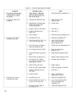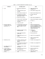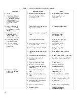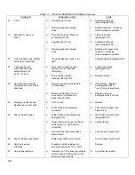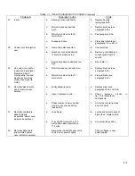
TABLE 7-1. 7035B TROUBLESHOOTING INDEX
PROBLEM
POSSIBLE CAUSE
CURE
1.
One position of pen produces
"Dirty" slidewire. High contact
Clean slidewire (see paragraph 5-11).
excessive jitter that repeats
resistance between slidewire
each time the pen reaches
wiper and either resistance ele-
this position.
ment or pickoff strip.
2.
Excessive pen jitter (small
a.
Amplifier gain adjusted too high.
a.
Adjust (lower) gain per
amplitude).
paragraph 5-92.
b.
Strap between front panel guard
b.
Connect strap.
terminal and negative input
terminal disconnected.
c.
Excessive common mode signal.
c.
See Table 1-1.
d.
Excessive differential input
d.
See Table 1-1.
signal noise.
e.
"Dirty" slidewire.
e.
Clean slidewire (see paragraph 5-11).
3.
Excessive Y-axis retrace
a.
Amplifier gain too low.
a.
Adjust gain (paragraph 5-92).
hysteresis (any slope).
b.
Source impedance too high (1 mv/
b.
Lower source impedance
inch, 0.4 mv/cm) range only.
and/or increase amplifier
gain (paragraph 5-92).
c.
Drive string too loose. Measure
c.
Tighten drive string (paragraph 5-67).
tension per paragraph 5-66.
d.
Pen carriage wheels set too tight.
d.
Adjust pen carriage (per
paragraph 5-71).
e.
Insufficient backlash in gears (too
e.
Adjust backlash (paragraph 5-69).
tight).
f.
Motor brushes excessively worn.
f.
Replace brushes (paragraph 5-38).
g.
Pen speed too fast. Retrace
g.
Decrease retrace pen speed.
error should be small only at pen
speeds below 1 inch/sec.
h.
Bearing in drive train faulty.
h.
Replace bearing.
i.
Faulty neon bulb in photochopper.
i.
Replace bulk (aging not required).
j.
Excessive differential noise on
j.
See Table 1-1.
input signal.
k.
Excessive friction.
k.
Clean and lubricate per
paragraphs 5-9 and 5-13.
4.
Excessive X-axis retrace
a.
Amplifier gain too low.
a.
Adjust gain (paragraph 5-92).
hysteresis (any slope).
b.
Source impedance too high (1 mv/
b.
Lower source impedance and/
inch, 0.4 mv/cm) range only.
or increase amplifier gain
(paragraph 5-92).
c.
Drive belt too loose. Measure
c.
Tighten belt (paragraph 5-79).
per paragraph 5-78.
7-2
Содержание HP-7035B
Страница 1: ...TECHNICAL MANUAL HEWLETT PACKARD MODEL HP 7035B ...
Страница 9: ...FIGURE 1 4 DIMENSION DRAWING FIGURE 1 5 ACCESSORIES 1 3 ...
Страница 12: ...FIGURE 1 7 TYPICAL FREQUENCY RESPONSE INPUT FILTER FIGURE 1 8 TYPICAL DYNAMIC RESPONSE 1 6 ...
Страница 14: ...FIGURE 2 1 WING BRACKET INSTALLATION FIGURE 2 2 STACKED CONFIGURATION 2 2 ...
Страница 16: ...FIGURE 3 1 FRONT PANEL CONTROLS 7035B AND 7035B 001 MODELS 3 2 ...
Страница 20: ...FIGURE 4 1 BLOCK DIAGRAM FIGURE 4 2 DETAILED BLOCK DIAGRAM 4 2 ...
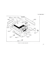
Страница 48: ...TM 11 6625 2850 14 P FIGURE 6 1 EXPLODED VIEW CABINET 6 9 ...
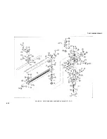
Страница 49: ...TM 11 6625 2850 14 P FIGURE 6 2 EXPLODED VIEW CARRIAGE ARM SHEET 1 OF 2 6 10 ...
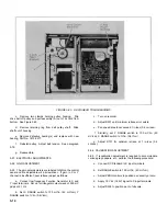
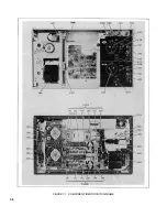
Страница 58: ...FIGURE 7 1 COMPONENT IDENTIFICATION FRAME 7 8 ...
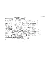
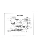
Страница 59: ...TM 11 6625 2850 14 P Figure 7 2 Component Identification Circuit Board 7 9 ...
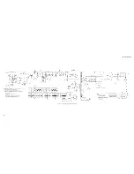
Страница 60: ...TM 11 6625 2850 14 P Figure 7 3 Schematic Model 7035B D 07035 92550 7 10 ...
Страница 62: ...TM 11 6625 2850 14 P FIGURE 8 1 COMPONENT IDENTIFICATION CIRCUIT BOARD 8 2 ...
Страница 66: ...TM 11 6625 2850 14 P FIGURE 8 5 EXPLODED VIEW CARRIAGE ARM 8 6 ...

